


Using The TPA0103 EVM With the Plug-N-Play Evaluation Platform
3-8
Details
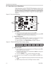
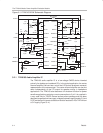
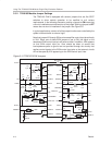
3.3.2 TPA0103 Module Jumper Settings
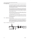
The TPA0103 EVM is equipped with several jumpers that act like SPST
switches to allow module operation to be modified to suit various
requirements. In the following discussion, setting a jumper to
ON
means that
a shunt is installed across the two pins of the jumper. Setting a jumper to
OFF
means that no shunt is installed on the jumper. See Figure 3.5.
In typical applications, some or all of the jumper functions are controlled by the
system microcontroller or external logic.
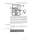
Note that jumpers S2 through S5 tie various amplifier control input pins directly
to V
DD
. When one of these EVM jumpers is set to ON, the signal on the
associated EVM control input pin will have no effect. In addition, V
DD
appears
on that EVM control input pin. Care should be taken to ensure that
low-impedance paths to ground are not provided through the circuitry that
applies control signals to the EVM control input pins or that external circuits
will not be upset by V
DD
appearing on the EVM control input lines.
Figure 3–5. TPA0103 EVM Jumpers
GND/HSGND/HS
S2
NCNC
ROUT+LOUT+
RLINE INLLINE IN
HP/LINEMUTE OUT
COUT–COUT+
MODE AMODE B
GND/HSGND/HS
RHP INLHP IN
RBYPASSCIN
V
DD
V
DD
NCSHUTDOWN
10
9
12
11
6
5
8
7
2
1
4
3
23
22
21
20
19
18
17
16
15
14
13
24
R6
100 kΩ
R4
20 kΩ
R3
20 kΩ
C2
1 µF
C1
1 µF
R1
20 kΩ
R2
20 kΩ
C3
5 pF
V
DD
R5
100 kΩ
C5
2.2 µF
S1
COUT+
MODE B
LIN
LINHP
V
DD
LOUT+
R10
20 kΩ
C7
1 µF
C9
2.2 µF
R9
20 kΩ
C8
5 pF
C6
1 µF
R8
20 kΩ
S3
LV
DD
S4
V
DD
ROUT+
RIN
RINHP
V
DD
HP/L*
COUT–
MODE A
S5
C10
2.2 µF
C11
10 µF
R13
200 kΩ
R15, 20 kΩ
R18
20 kΩ
R17
200 kΩ
C12
5 pF
R16
20 kΩ
R7
20 kΩ
R14
200 kΩ
GND
R11
100 kΩ
R12, 100 kΩ
TPA0103