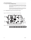
Using The TPA0103 EVM With the Plug-N-Play Evaluation Platform
3-9
Details
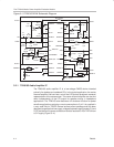
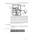
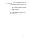
3.3.2.1 S1 — Shutdown Jumper
To have the module amplifier IC enter the shutdown mode when the module
mute control input is activated, set shutdown jumper S1 to ON.
The mute control output pin on the TPA0103 amplifier IC goes high when the
mute mode is selected by the output mode jumpers (S2 and S4). Jumper S1
connects the mute output pin to the shutdown control input pin of the IC so that
when S1 is ON, the IC is forced into shutdown mode instead of mute mode
when the mute mode is selected. When S1 is OFF, a pulldown resistor on the
module holds the IC shutdown control input pin low, keeping the IC out of the
shutdown mode.
The shutdown mode reduces IC current consumption to approximately 5 µA
compared to approximately 1.5 mA in the mute mode. It takes longer, however,
to resume normal operation from the shutdown mode (approx. 1 s to 2 s) than
it takes to resume normal operation from the mute mode (approx. 100 ms to
500 ms).
3.3.2.2 S2 and S4 — Output Mode Control Jumpers
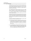
Two IC amplifier output mode control pins select among three output modes
and mute. These pins, Mode A and Mode B, are brought out to module pins
and also have jumpers that can hardwire the IC amplifier control inputs high.
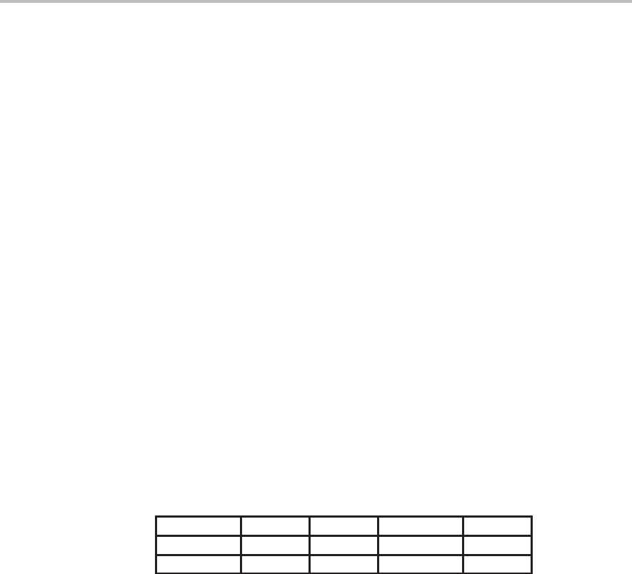
Table 3–2 shows the relationship between the IC amplifier control inputs and
the output modes.
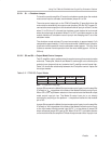
Table 3–2. TPA0103 Output Modes
TERMINAL 3-Channel Mute Center Only L/R Only
MODE A L H L H
MODE B L L H H
Note: L = logic low, H = logic high
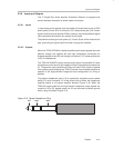
Jumper S2 connects the Mode B output mode control input pin on the amplifier
IC directly to V
DD
regardless of the state of the Mode B module control input.
When S2 is OFF, a pulldown resistor on the module holds the Mode B output
mode control input pin low. The Mode B control input pin is not directly
controlled by anything on the platform — the platform socket for that module
pin is N/C.
Jumper S4 connects the Mode A output mode control input pin on the amplifier
IC directly to V
DD
regardless of the state of the Mode A module control input,
or the input select module control input (HP/L*), or the status of jumper S3
when autosense jumper S5 is set to ON. When S4 is OFF, a pulldown resistor
on the module holds the amplifier IC Mode A output mode control input pin low.


