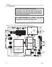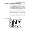
Using The TPA0103 EVM With the Plug-N-Play Evaluation Platform
3-10
Details
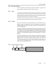
3.3.2.3 S3 — Input Select Jumper
To select the line inputs, set input select jumper S3 to OFF. To select the
headphone inputs, set input select jumper S3 to
ON.
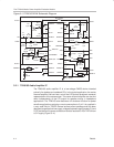
The TPA0103 amplifier IC has two separate inputs for each of the left and right
stereo channels. An internal multiplexor selects which input will be connected
to the amplifier based on the state of the HP/LINE
pin on the IC. However, the
EVM HP/L* control input pin is not directly controlled by anything on the
platform — the platform socket for that module pin is N/C. The amplifier IC
HP/LINE
control pin can be tied high manually via jumper S3 or connected to
the amplifier IC Mode A control pin via jumper S5 so that it follows that control
signal.
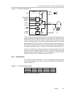
For manual control, jumper S3 connects the HP/L* module control input pin to
V
DD
, so that when S3 is ON, the headphone inputs are selected. When S3 is
OFF, a pulldown resistor on the module holds the IC shutdown control input
pin low, selecting the line inputs.
3.3.2.4 S5 — Autosense Jumper
To have the IC amplifier input select control input pin (HP/Line) follow the state
of the Mode A IC output mode select pin, set autosense jumper
S5
to ON
.
This
automatically selects the headphone inputs when the Mode A control input
goes high.
Note that when autosense jumper S5 is set to ON, amplifier IC control input
pins HP/Line
and Mode A are tied to V
DD
, and the Mode A control signal will
have no effect if
either
jumper S3 or jumper S4 are set to ON.


