18
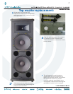
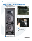
Amplifi er assembly replacement continued:
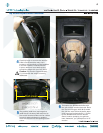
6
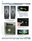
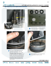
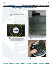
Closeups of the led PCB cable and
connector are shown above. The black
wire of the cable is closest to the edge of
the amplifi er assembly. The cable only fi ts
in one way.
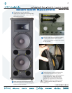
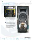
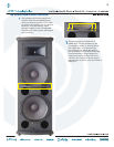
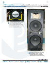
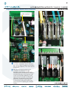
7
See the pictures to the right for the
closeups of the woofer and high
frequency driver terminals. Make sure
the cables are reconnected to the same
terminals they were removed from (but
on the new amplifi er assembly). Once
again, they are: (2) blue and black, (3)
solid blue, (4) solid black, and (5) solid
yellow. Do not force cable removal
or connection, although needle-nose
pliers may aid in loosening the crimped
cables.
1
Edge of
amplifi er
assembly
1
Edge of
amplifi er
assembly
2
Edge of amplifi er assembly
34
5
2
Edge of amplifi er assembly
3
4
5