© Titan Tool Inc. All rights reserved. 11
12. Using two wrenches, hold the nut on one of the outer
diaphragm disks while using the other wrench to loosen
and remove the opposite outer diaphragm disk.
13. Remove the diaphragm that was released by the removal
of the rst outer diaphragm disk.
14. Pull the opposite side diaphragm that is still assembled to
the shaft out of the pump motor.
15. Place the shaft into a vice. Use caution when securing the
shaft in the vice so that the shaft is not damaged.
16. Using a wrench, loosen and remove the remaining outer
diaphragm disk.
17. Remove the remaining diaphragm from the shaft.
18. Place one of the new diaphragms onto the shaft. Thread
the corresponding outer diaphragm disk into the shaft and
tighten securely.
19. Remove the shaft with the assembled diaphragm from the
vise.
20. Lubricate the shaft with grease and slide it through the
pump motor.
21. Place the remaining new diaphragm onto the shaft.
Thread the corresponding outer diaphragm disk into the
shaft.
22. Using two wrenches, hold the nut on the opposite outer
diaphragm disk while using the other wrench to tighten the
remaining outer diaphragm disk securely.
23. Using the six diaphragm cover nuts, screws, and washers
on each, reassemble the two diaphragm covers to each
side of the pump motor. TIghten the nuts securely.
24. Using the four manifold nuts, screws, and washers,
reassemble the suction manifold to the bottom of the
pump. Make sure the manifold is positioned in the same
orientation as it was before it was removed.
25. Using the four manifold nuts, screws, and washers,
reassemble the delivery manifold to the top of the
pump. Make sure the manifold is positioned in the same
orientation as it was before it was removed.
26. Carefully slide the pump back into position on the cart.
Make sure to align the uid pipe with the appropriate hole
on the front plate before positioning the pump.
27. Using the four lock nuts and carriage screws, secure the
pump to the cart.
28. Replace the uid outlet tting onto the front panel.
29. Reattach the air line from the radiator manifold to the
tting on the pump.
30. Replace the hopper onto the cart and uid inlet assembly.
Use the cart handles as guides to position the hopper
down onto the uid inlet assembly.
Replacing the Reversing Valve
Use the following procedure to replace the reversing valve in the
double diaphragm pump.
1. Remove the pump from the sprayer as described in the
corresponding “Replacing the Diaphragms” procedure in
this section.
2. Remove the four manifold nuts, screws, and washers
that secure the delivery manifold to the top of the pump.
Remove the delivery manifold.
3. Remove the four nuts and washers from the screws that
secure the pressure side cover to the motor. Pull the
pressure side cover off of the screws.
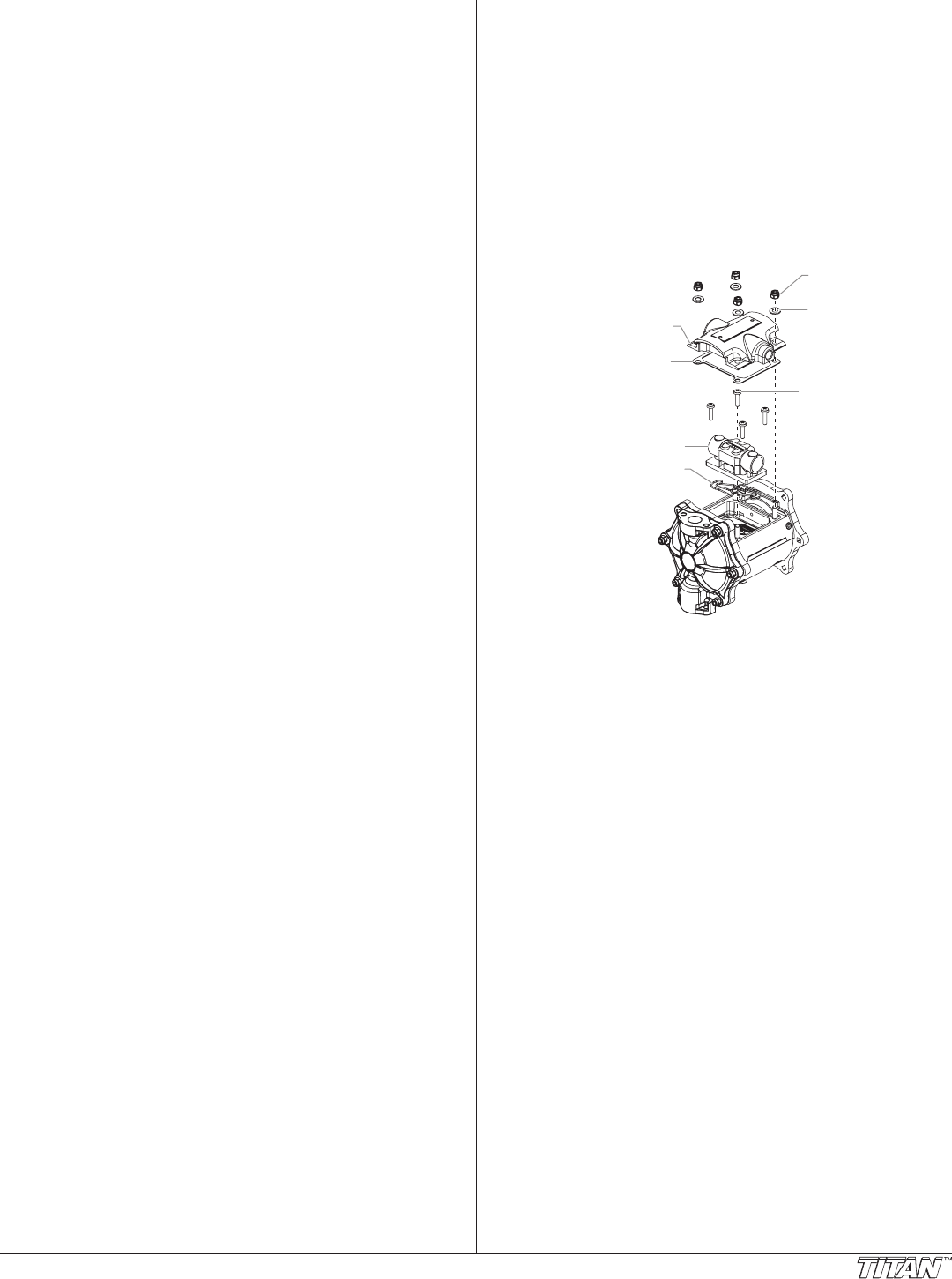
4. Remove the four valve screws that secure the reversing
valve to the motor. Remove the reversing valve.
Pressure Side Cover
Pressure Gasket
Reversing Valve
Reversing Valve
Screw
Pressure Cover
Nut
Pressure Cover
washer
Reversing Valve
Gasket
5. Using a jet of compressed air, blow out the inside of the
motor.
6. Making sure the reversing valve gasket is positioned
properly, position the new reversing valve inside
the motor. Make sure that the shoe is in the “end of
stroke” position (both vertically and horizontally) before
assembling the valve.
7. Using the four valve screws, secure the reversing valve to
the motor.
8. Place the pressure side cover onto the four screws that
secure it to the motor. Secure the pressure side cover
using the four washers and nuts. Tighten securely.
9. Using the four manifold nuts, screws, and washers,
reassemble the delivery manifold to the top of the
pump. Make sure the manifold is positioned in the same
orientation as it was before it was removed.
10. Replace the pump onto the sprayer as described in the
corresponding “Replacing the Diaphragms” procedure in
this section.


