Replacing the Transducer
Electrostatic discharge (ESD) potential could cause
damage to electronic pressure control. Use Titan ESD
wrist strap P/N 700-1037 or equivalent when working on
electronic pressure control.
1. Perform the Pressure Relief Procedure.
2. Using a Phillips
screwdriver, remove
the four screws that
secure the electronic
pressure control
(EPC) assembly to the
EPC housing.
Carefully remove the
EPC assembly from
the housing. Gently
move the assembly
away from the sprayer
and allow the assembly to hang from the housing.
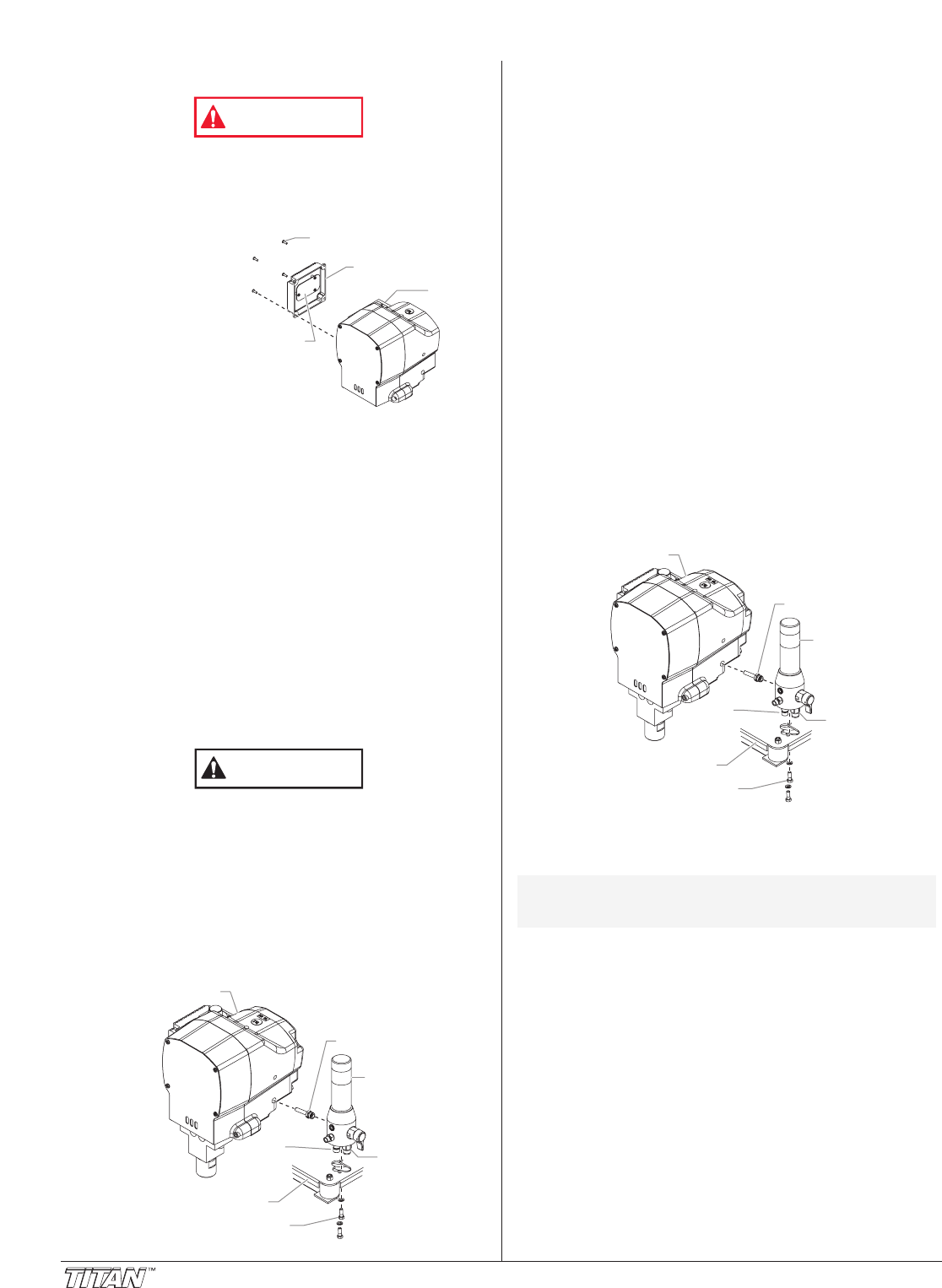
3. Locate the transducer wire in the EPC housing. This wire
will be protruding from a hole in the lower left hand corner
of the EPC housing. Disconnect this wire from the EPC
board (it has a phone jack-style connector).
4. Break off the locking tab from the phone jack-style
connector at the end of the transducer wire.
5. Using a 7/8” open-end wrench, loosen and remove the
fluid hose from the fitting on the bottom of the filter
assembly.
6. Remove the return hose from the fitting on the bottom of
the filter assembly.
7. Using a 1/2” socket, remove the two hex screws that
secure the filter assembly to the cart.
8. Lift the filter assembly off the cart so that the transducer
tube moves out of the hole in the gear housing. Gently
pull the transducer wire through the housing until it is fully
disengaged from the hole.
9. Mount the filter assembly in a vise for easy access to the
transducer.
Do not over-tighten the vise.
10. Using a 3/4” open-end wrench, turn the transducer nut
counterclockwise to remove the transducer from the filter
housing.
11. Locate the new transducer. Make sure that there is a
white, PTFE o-ring on the end of the transducer that gets
inserted into the filter housing.
12. Insert the transducer into the filter housing port. Rotate
the transducer nut clockwise to tighten it into the filter
housing. Torque the nut to 360–400 in./lbs.
13. Remove the filter assembly from the vise.
Transducer
Filter Assembly
Hex Screw
Gear Housing
Filter
Assembly
Fluid
Hose
Fitting
Cart
Return
Hose
Fitting
CAUTION
EPC
Housing
EPC Assembly Screw
EPC Assembly
EPC
Board
WARNING
10 ©Titan Tool Inc. All rights reserved.
14. Insert the phone jack-style connector on the new
transducer wire into the hole in the gear housing from
which the old transducer wire was removed. Push the
wire and connector until the connector is visible in the
EPC housing.
15. Gently pull the wire into the EPC housing while moving
the filter assembly to its mounting point on the cart. Guide
the end of the transducer tube into the hole in the gear
housing.
16. Mount the filter assembly to the cart using the two hex
screws and lock washers. Torque the screws to 100–130
in./lbs.
17. Using a 7/8” open-end wrench, attach the fluid hose to the
fitting on the bottom of the filter assembly. Tighten
securely.
18. Push the return hose firmly into the fitting on the bottom of
the filter assembly. Pull on the hose to make sure it has
engaged within the fitting.
19. Plug the phone jack-style connector on the transducer
wire into the socket on the EPC board from which the old
connector was removed.
20. Carefully place the EPC assembly over the EPC housing
taking care not to pinch any wires.
21. Install the four screws that secure the EPC assembly to
the EPC housing. Tighten securely.
22. Take the sprayer to a Titan Authorized Service Center for
re-calibration.
23. After re-calibration, pressurize the system and check for
leaks.
Servicing the Clutch Assembly
Removing/Replacing the Clutch Armature
Assembly
1. Perform the Pressure Relief Procedure.
2. Using a 11/16” open-end wrench, loosen and remove the
fluid hose from the fitting on the back of the fluid section.
3. Hold the transducer tube with a pliers to prevent it from
rotating and turn the transducer nut counterclockwise
using a 3/4” open-end wrench. When the nut disengages
the filter housing, carefully remove the transducer from the
filter housing.
4. Locate the wire that exits the rear of the electronic
pressure control (EPC) housing and connects to the wire
harness on the engine. Disconnect this wire from its
connector at the engine wire harness.
5. Using a 1/2” wrench, remove the four hex screws and lock
washers that secure the clutch housing to the gear housing.
6. Using a 9/16” socket, remove the two hex screws that
secure the gear housing to the cart.
NOTE: When replacing the clutch armature, the clutch
rotor must be replaced also. This will allow for
even wear and maximum life on clutch parts.
Transducer
Filter Assembly
Hex Screw
Gear Housing
Filter
Assembly
Fluid
Hose
Fitting
Cart
Return
Hose
Fitting


