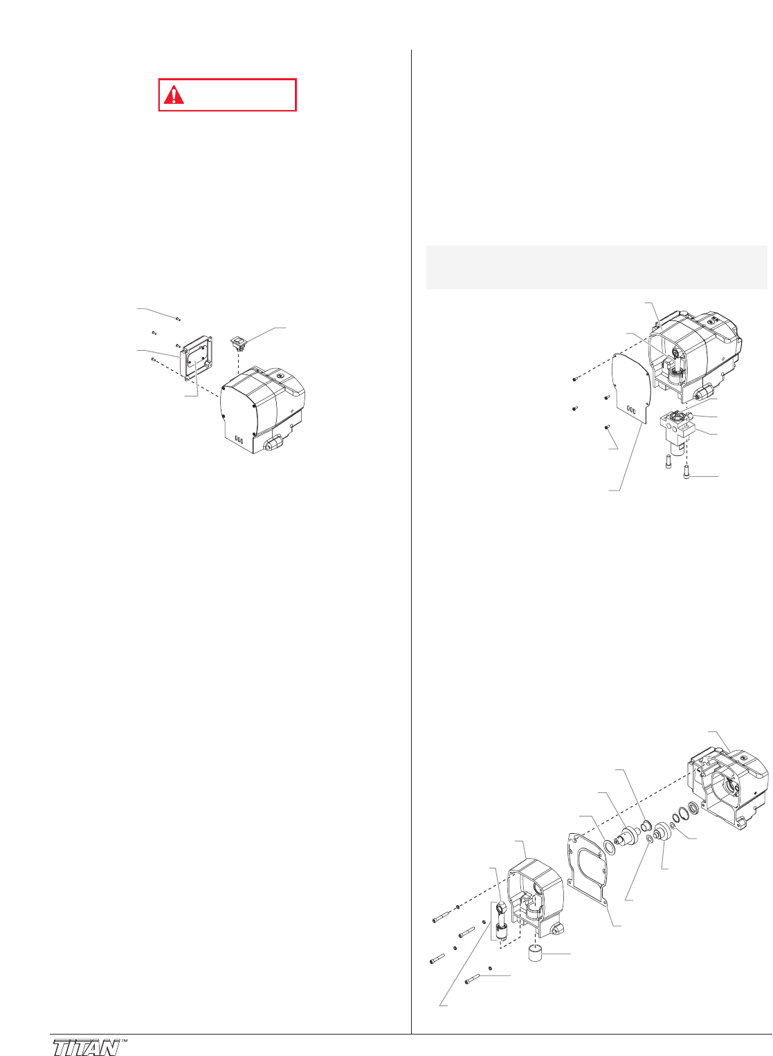
Replacing the Pump ON/OFF Switch
Electrostatic discharge (ESD) potential could cause
damage to electronic pressure control. Use Titan ESD
wrist strap P/N 700-1037 or equivalent when working on
electronic pressure control.
1. Perform the Pressure Relief Procedure.
2. Using a Phillips screwdriver, remove the four screws that
secure the electronic pressure control (EPC) assembly to
the EPC housing. Carefully remove the EPC assembly
from the housing. Gently move the assembly away from
the sprayer and allow the assembly to hang from the
housing.
3. Locate the bottom of the pump ON/OFF switch inside the
EPC housing.
4. Disconnect the switch wires from the pump ON/OFF
switch. Remember the locations of each of the two wires
(label the wires, if necessary).
5. Depress the mounting tabs on each corner of the pump
ON/OFF switch inside the EPC housing and remove the
switch through the top of the housing.
6. Snap the new pump ON/OFF switch into the switch hole
in the EPC housing.
7. Connect the two switch wires to the new pump ON/OFF
switch. Make sure the wires are connected to the
corresponding terminals from which they were removed
(refer to the labels created earlier in this procedure or the
electrical schematic in the Parts List section of this
manual).
8. Carefully place the EPC assembly over the EPC housing
taking care not to pinch any wires.
9. Install the four screws that secure the EPC assembly to
the EPC housing. Tighten securely.
Pump ON/OFF
Switch
EPC
Board
EPC
Assembly
EPC
Assembly
Screw
8©Titan Tool Inc. All rights reserved.
Replacing the Gears and/or
Slider Assembly
1. Using a Phillips screwdriver, remove the four front cover
screws. Remove the front cover.
2. Start the engine (refer to the procedures in the Operation
section of this manual). Turn the pressure control knob
clockwise to its maximum pressure setting.
3. Toggle the pump ON/OFF switch between the ON and
OFF positions in short bursts until the slider assembly and
piston stop at the bottom of their stroke (in their lowest
position).
4. Turn off the engine and perform the Pressure Relief
Procedure.
5. Using a 11/16” open-
end wrench, loosen
and remove the fluid
hose from the fitting
on the back of the
fluid section.
6. Using a 3/8” hex
wrench, remove the
two socket screws
that secure the fluid
section to the pump
housing.
7. Remove the fluid
section by pulling it
straight down from
the pump housing
until the dowel pins
on the pump housing disengage from the fluid section
housing. Then, pull the fluid section forward to disengage
the piston from the T-slot on the slider assembly.
8. Using a 1/4” hex wrench,.remove the four socket screws
that secure the pump housing to the gear housing.
9. Slide the pump housing away from the gear housing.
10. Remove and clean the housing gasket. Replace if
damaged.
11. Slide the crankshaft assembly, with the two thrust washers
out from the gear housing side of the pump housing.
12. Remove the output gear assembly with the two thrust
washers.
13. Thoroughly clean the crankshaft assembly, the output
gear assembly, and all the thrust washers.
Connecting
Rod
Slider Bushing
Slider Assembly
Gear Housing
Pump Housing
Output Gear
Assembly
Thrust
Washer
Thrust Washer
Housing Gasket
Large Thrust Washer
Crankshaft Assembly
Cylindrical Thrust Washer
Pump Housing
Socket Screw
Fitting
Piston
Pump
Housing
Slider
Assembly
Front
Cover
Screw
Fluid
Section
Housing
Socket
Screw
Front
Cover
NOTE: If replacing the slider assembly, the fluid
section must be removed from the pump
housing.


