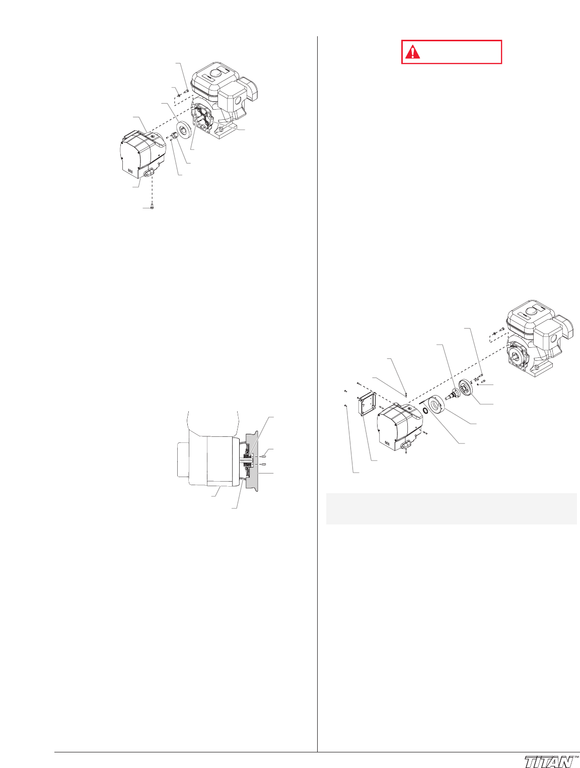
7. Slide the pump and gear housings away from the engine
to disengage them from the clutch housing.
8. Locate the clutch armature assembly on the end of the
engine shaft. Note the two set screws as well as the
unused, threaded hole in the taper lock bushing at the
center of the clutch hub.
9. Using an 1/8” hex wrench, remove the two set screws
from the taper lock bushing
10. Thread one of the set screws into the unused, threaded hole
on the taper lock bushing. As the screw tightens, the bushing
will loosen. Once the bushing has loosened enough, slide the
clutch armature assembly off the engine shaft.
11.To replace the clutch armature assembly , line up the
three holes in the taper lock bushing with the three holes
in the clutch armature and insert the bushing into the
center of the clutch armature.
12. Line up the key on the taper lock bushing with the keyway
on the engine shaft and slide the assembly onto the shaft
with the holes facing out.
13. Apply blue Loctite to the two set screws and insert the
screws into the taper lock bushing. Tighten the set screws
only two turns at this time.
15. Using the clutch set-up
tool (P/N 755-194),
position the clutch
armature on the engine
shaft. Hold the tool
across the face of the
clutch housing so that
the center, recessed
portion of the tool
straddles the clutch
armature assembly. Pull
the clutch armature
assembly towards the
tool until the face of the armature is against the tool.
15. While holding the clutch armature assembly against the
tool, use an 1/8” hex wrench and alternately tighten the
set screws into the taper lock bushing. Torque to 65–75
in/lbs.
16. Make sure the friction surface of the clutch armature is
clean and free from oil or grease.
Removing the Clutch Rotor, Clutch Field, and
Drive Shaft Assembly
1. Follow steps 1–7 in “Removing/Replacing the Clutch
Armature Assembly.”
2. Locate the clutch rotor assembly, which will be protruding out
from the gear housing. Note the locations of the three socket
screws and the two empty, threaded holes on the clutch rotor.
3. Using a 3/16” hex wrench, remove the three socket
screws and lock washers that secure the clutch rotor to
the drive shaft assembly.
4. Thread two of the socket screws into the empty, threaded
holes and tighten alternately. This will push the clutch
rotor away from the drive shaft assembly and pinion.
Clutch
Housing
Engine
Set
Screw
Set-Up
Tool
Taper
Lock
Bushing
Taper Lock Bushing
Gear
Housing
Clutch Armature
Pump
Housing
Lock Washer
Clutch
Housing
Clutch Housing
Hex Screw
Set Screw
Engine Shaft
Gear Housing
Hex Screw
Electrostatic discharge (ESD) potential could cause
damage to electronic pressure control. Use Titan ESD
wrist strap P/N 700-1037 or equivalent when working on
electronic pressure control.
5. Using a Phillips screwdriver, remove the four screws that
secure the EPC assembly to the EPC housing. Carefully
remove the EPC assembly from the housing.
6. Locate the two clutch field wires that pass from the gear
housing into the EPC housing through a grommet in the
back of the EPC housing. Remember the wire connection
terminals on the EPC assembly (label if necessary) and
disconnect the wires. Gently move the EPC assembly
away from the housing and rest it on the work surface by
the control housing.
7. Locate the four pairs of set screws that secure the clutch
field to the gear housing. They are located on the exterior
of the gear housing at the 12, 3, 6, and 9 o’clock positions
while facing the clutch field end of the gear housing.
Using an 1/8” hex wrench, remove the setscrews.
Remember the location of the two clutch field wires with
respect to the grommet and EPC housing.
8. Carefully slide the clutch field out of the gear housing,
keeping the field square to the gear housing so it does not
bind.
9. Using a Phillips screwdriver, remove the four front cover
screws. Remove the front cover.
10. Using a 11/16” open-end wrench, loosen and remove the
fluid hose from the fitting on the back of the fluid section.
11. Using a 1/4” hex wrench,.remove the four socket screws
that secure the pump housing to the gear housing.
12. Slide the pump housing away from the gear housing.
13. Remove and clean the housing gasket. Replace if
damaged.
14. Locate the drive shaft pinion that is protruding from the
front side of the gear housing. Remove the small snap
ring that is located on the drive shaft hub in front of the
ball bearing that is supporting the drive shaft.
15. From the opposite side of the gear housing (clutch side)
slide the drive shaft assembly out of the gear housing.
16. Inspect the grease seal located inside the bore from which
the drive shaft was removed. Replace if worn or
damaged. To remove the grease seal, use a flat blade
screwdriver to carefully pry the seal from the bore.
17. Clean the inside of the gear housing.
NOTE: To remove the drive shaft assembly, the pump
housing first must be removed from the gear
housing.
Clutch Rotor Socket Screw
Drive Shaft Assembly
Pointed Set
Screw
Set Screw
Clutch Field
Assembly
Lock
Washer
Clutch
Rotor
Clutch Field
Wires
EPC Assembly
EPC Assembly Screw
©Titan Tool Inc. All rights reserved. 11


