22 © Titan Tool Inc. All rights reserved.
8. Pre-lubricate the piston and valve rod assembly with
Coolflo™ hydraulic fluid (P/N 430-361). Install hydraulic
piston rod (21) into motor pump block (25) with a gently
pushing and rotating motion to work the hydraulic piston rod
in through the seal (24).
9. Replace the connecting rod pin and retainer ring. See
illustration below.
10. Install o-ring (12) on cylinder wall. Lubricate ring and inner
wall. With the hydraulic piston rod held firmly, the cylinder
should be gently driven over the piston seal with a rubber
mallet. Tightly thread the cylinder into motor pump block (25).
11. Raise hydraulic piston rod (21) to top position and thread lock
ring (22) all the way up on upper threads of cylinder (23).
12. Pull valve rod assembly (20) up as far as it will travel and
grasp it with vise grip pliers. Then install cylinder head (11),
already assembled, over valve rod until the top threads of
the valve rod pass through the top of the spool/sleeve set
(5). The valve rod threads must be clean and free of oil.
Place one drop of blue Loctite on threads of flex lock nut (9)
and thread nut onto valve rod to full tight position (do not
over-tighten) while holding valve rod below with vise grip
pliers.
13. Thread cylinder head (11) down onto the cylinder (23) and
then back off just enough to reassemble hydraulic fittings
and motor tube (26). Tighten lock ring with spanner wrench
to hold cylinder head in position.
14. The tee assembly (27) and the elbow (15) use an o-ring
(27a) to seal on the outer diameter (O.D.) of the motor tube
(26). The O.D. of the motor tube should be free of scratches
or sharp edges. The lock nuts on these fittings first should
be hand tightened, then wrench tightened another half turn.
15. Install o-ring (8) onto cylinder head plug (7). Tighten.
Motor Service Kit, Minor (P/N 235-050)
Item
Part # Description Quantity
2 141-007 O-ring....................................................2
3 325-005 Trip spring.............................................2
4 569-016 Ball, SS.................................................2
6 441-152 O-ring....................................................3
8 441-217 O-ring....................................................1
9 858-811 Flex lock nut .........................................1
12 431-032 O-ring....................................................2
18 235-027 Piston seal ............................................1
19 235-026 O-ring....................................................1
24 235-028 Rod seal................................................1
Connecting Pin Arrangement
NOTE: Inspect the bottom of hydraulic piston rod (21)
for nicks or sharp areas that could damage the
piston seal during installation through the pump
block (25).
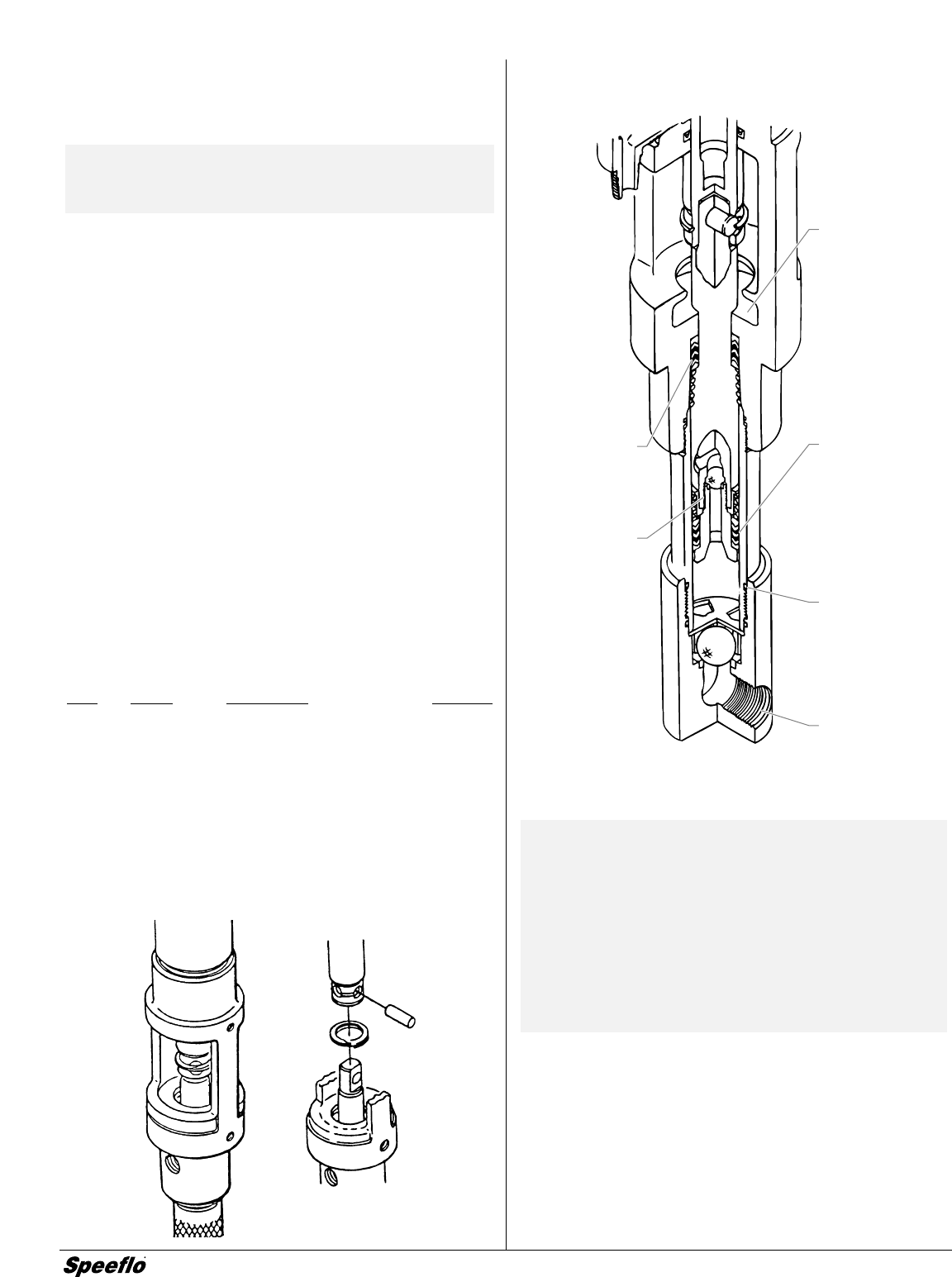
Fluid Pump
Fluid Pump Service Instructions
IMPORTANT: Use of non-Speeflo manufactured service
parts my void warrranty. Ask for original
parts made by Speeflo for best services.
The 107 Series Pump should receive a
routine servicing after approximately 1,000
hours of use. Earlier servicing is required
if there is excessive leakage from the top
packing or if pump strokes become faster
on one stroke or the other. The use of
Speeflo Piston Lube (P/N 700-925) is
recommended as an upper packing
lubricant. Do not substitute oil, water, or
solvent for an upper packing lubricant.
Peaks of upper
packings must
face up.
Torque piston
retainers to
75 ft./lbs.
(1095 N/m).
Use blue
Loctite.
Wet cup area
for piston lube
packing
lubricant.
Peaks of lower
packings must
face down.
Lubricate O-ring.
37)( tape
siphon hose


