45-EN
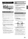
To prevent noise/interference in the audio system.
• Locate the unit and route the leads at least 10 cm away from the car harness.
• Keep the battery power leads as far away from other leads as possible.
• Connect the ground lead securely to a bare metal spot (remove any paint, dirt or grease if necessary) of the car chassis.
• If you add an optional noise suppressor, connect it as far away from the unit as possible. Your Alpine dealer carries various noise
suppressors, contact them for further information.
• Your Alpine dealer knows best about noise prevention measures so consult your dealer for further information.
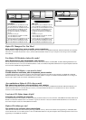
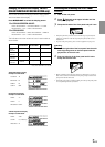
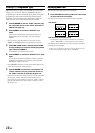
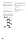
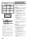
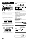
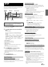
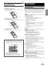
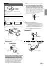
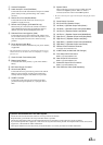
The X-Over Switch position for a two-way system
(frequency range is divided between highs for front/rear and
lows for the Subwoofer).
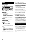
The X-Over Switch position for a three-way system whose
frequency range is divided among the highs (Front), mids
(Rear), and lows (Subwoofer).
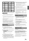
• Use the SUB-W output cord to connect the unit to the low range speaker.
• You can use the built-in amplifier to output the front output/rear output.
• You cannot adjust the fader when set to 3WAY.
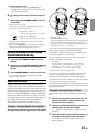
The position of the X-Over switch : F/R/Sub-W
The position of the X-Over switch: 3WAY
Output of this unit :
Front output Rear output SUB-W output
High range
speaker (L)
Mid range
speaker (L)
High range
speaker (R)
Mid range
speaker (R)
Low range
speaker (L)
Low range
speaker (R)
Front high range
speaker (L)
Rear high range
speaker (L)
Front high range
speaker (R)
Rear high range
speaker (R)
Low range
speaker (L)
Low range
speaker (R)
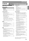
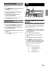
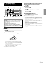
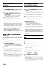
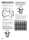
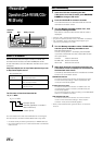
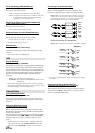
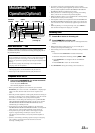
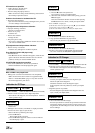
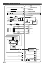
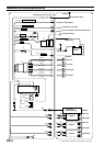
1 Antenna Receptacle
Connect to the supplied ISO antenna convertor plug.
2 Audio Interrupt In Lead (Pink/Black)
Connect this lead to the Audio Interface output of a cellular
phone which provides ground shorting when a call is
received.
3 Remote Turn-On Lead (Blue/White)
Connect this lead to the remote turn-on lead of your
amplifier or signal processor.
4 Dimmer Lead (Orange)
This lead may be connected to the vehicle’s instrument
cluster illumination lead. This will enable the vehicle’s
dimmer control to dim the backlighting of the unit.
5 Switched Power Lead (Ignition) (Red)
Connect this lead to an open terminal on the vehicle’s fuse
box or another unused power source which provides (+) 12V
only when the ignition is turned on or in the accessory
position.
6 Power Antenna Lead (Blue)
Connect this lead to the +B terminal of your power antenna,
if applicable.
• This lead should be used only for controlling the vehicle's power
antenna. Do not use this lead to turn on an amplifier or a signal
processor, etc.
7 Choke Coil with Fuse Holder (20A)
8 Battery Lead (Yellow)
Connect this lead to the positive (+) post of the vehicle's
battery.
9 ISO Power Supply Connector
! Ground Lead (Black)
Connect this lead to a good chassis ground on the vehicle.
Make sure the connection is made to bare metal and is
securely fastened using the sheet metal screw provided.
" Ai-NET Connector
Connect this to the output or input connector of other
product (CD changer, Equalizer, etc.) equipped with Ai-
NET.
# System Switch
When connecting a processor using Ai-NET, place this
switch in the EQ/DIV position. When no device is
connected, leave the switch in the NORM position.
• Be sure to turn the power off to the unit before changing the switch
position.
$ Setting the 3WAY/2WAY switch
Set the 3way/2way Switch according to your audio system.
% Power Supply Connector
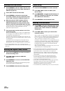
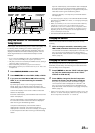
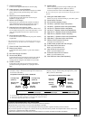
& ISO Connector (Speaker Output)
( Left Rear (+) Speaker Output Lead (Green)
) Left Rear (–) Speaker Output Lead (Green/Black)
~ Left Front (+) Speaker Output Lead (White)
+ Left Front (–) Speaker Output Lead (White/Black)
, Right Front (–) Speaker Output Lead (Grey/Black)
- Right Front (+) Speaker Output Lead (Grey)
. Right Rear (–) Speaker Output Lead (Violet/Black)
/ Right Rear (+) Speaker Output Lead (Violet)
: Remote Control Interface Connector
To remote control interface box.
; Ai-NET Cable (Included with CD Changer)
< Front Output RCA Connectors
RED is right and WHITE is left.
= Rear Output RCA Connectors
RED is right and WHITE is left.
> Subwoofer Output RCA Connectors
RED is right and WHITE is left.
? RCA Extension Cable (Sold Separately)