


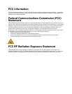


MVP-WDS Wall Docking Station & CB-MVPWDS Conduit Box
5
MVP-WDS Wall Docking Station for MVP Panels
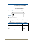
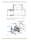
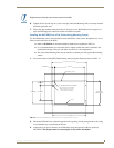
2. Using either nails or screws, fasten the conduit box to the stud through the five Stud Fastening
Holes.
3. Remove the wiring knockouts from the right side of the conduit box to accommodate cabling to the
MVP-WDS.
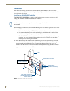
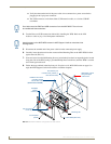
4. Thread the USB and Power cables through the knockouts on the right of the conduit box. It is
recommended that you test these connections before fully installing the WDS.
5. Install the drywall/sheetrock before inserting the MVP-WDS into the conduit box.
Removing the MVP-WDS Faceplate
The faceplate must be removed from the main MVP-WDS unit before any installation procedures can be
done. The unit is shipped without the Die Cut Foam covers (60-5965-47) installed over the two #6-32
Faceplate Security Screws. The foam covers are installed over the faceplate screws only after the
installation is complete and the support cradle is retracted.
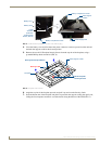
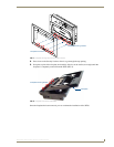
1. Place the MVP-WDS face up on a flat level surface.
2. Connect the mini-Phoenix connector from a compatible 12V power supply to the PWR connector
on the side panel (see FIG. 4) to apply power.
3. Open the Battery Compartment and press the Cradle Activation pushbutton (recessed white button
located near the pins in Battery Slot #2) to angle the Support Cradle forward (FIG. 5).
Although there are wiring knockouts are on both sides of the conduit box, the
knockouts on the right side will be used for the MVP-WDS (wall docking station)
connectors, so always secure the conduit box to the stud using the Stud Mounting
Holes on the left side of the box.
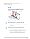
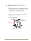
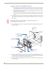
FIG. 4 MVP-WDS Docking Station components (front view)
Security Latch
Battery Compartment
MVP Interface Connector pins
Battery Compartment Latch
MVP Alignment Guide Pin
Security Release pushbutton/LEDs
MVP Support Cradle
Faceplate
USB connectors (2)
2-pin mini-Phoenix
power connector
MVP Alignment Guide Pin
Die Cut
Foam covers