


MVP-WDS Wall Docking Station & CB-MVPWDS Conduit Box
8
MVP-WDS Wall Docking Station for MVP Panels
Installing the MVP-WDS in a CB-MVPWDS Conduit Box
The conduit box must be mounted prior to continuing this section. Refer to the Installing the
CB-MVPWDS Conduit Box section on page 4 for detailed pre-wall installation instructions.
The faceplate must be removed prior to any surface installation (see the Removing the MVP-
WDS Faceplate section on page 5).
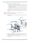
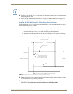
Verify that the USB and power cables have been threaded through the knockouts on the right
of the conduit box. Leave enough slack in the wiring to accommodate re-positioning of the
panel.
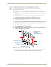
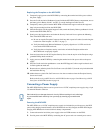
1. Connect the 2-pin power connector and USB cables to the WDS. The WDS must be installed with
these attached. The USB connectors can be from either a USB extension cable, or a wireless USB
RF transmitter.
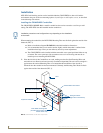
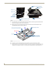
2. Insert the WDS into the conduit box, so that the Mounting Tabs on the WDS lie flush against the
conduit box (FIG. 9).
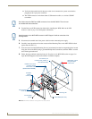
3. Using a grounded Phillips-head screwdriver, insert and secure four #4-40 Mounting Screws (not
included) into their corresponding holes located along the sides of the MVP-WDS until the WDS is
securely fastened to the conduit box, and is flush against the wall.
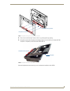
4. Follow the steps outlined in the Replacing the Faceplate on the MVP-WDS section on page 13 to re-
install the faceplate.
Verify that the terminal end of the power cable is not connected to a power source
before plugging in the 2-pin power connector.
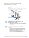
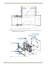
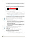
FIG. 9 MVP-WDS installation configuration within a CB-MVPWDS Conduit Box
MVP-WDS (Main unit)
#4-40 Mounting Screws
Faceplate
Mounting Tab
Die Cut Foam
CB-MVPWDS
Conduit Box
covers (2)
(four - not included)
secure the WDS
to the Conduit Box.
#6-32 Faceplate
Security Screws (2)