


MVP-WDS Wall Docking Station & CB-MVPWDS Conduit Box
9
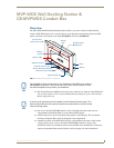
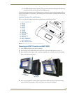
MVP-WDS Wall Docking Station for MVP Panels
Installing the MVP-WDS Using Expansion Clips
Expansion clips are mounted through the four oval holes located along the rim of the MVP-WDS. As the
screw is tightened, the clip bends toward the insertion hole and into the wall. This bending creates a
"grip" on the wall by either pressing onto the wall or by securing the drywall between the housing and
the drywall clip.
The faceplate must be removed prior to any surface installation (see the Removing the MVP-
WDS Faceplate section on page 5).
The outer frame Mounting Tabs must be flush against the mounting surface.
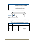
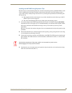
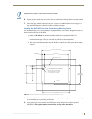
1. Cut out the surface for the WDS using the dimensions shown in installation diagram SP-5965-01
(reproduced in FIG. 10 on page 10). It is recommended that you cutout the surface slightly smaller
than what is outlined in the installation drawings so that you can make any necessary cutout
adjustments.
Be sure to cut out the four notches along the sides to accommodate the four drywall expansion clips
(included).
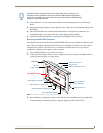
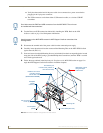
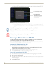
2. Thread the USB and Power cables through the surface opening, leaving enough slack in the wiring
to accommodate re-positioning of the unit.
3. Connect the 2-pin power connector and USB cables to the WDS. The WDS must be installed with
these attached. The USB connectors can be from either a USB extension cable, or a wireless USB
RF transmitter.
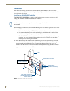
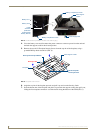
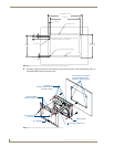
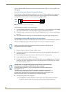
4. Install the four sets of drywall screws and expansion clips into the four oval notch locations along
both sides of the main unit (FIG. 11).
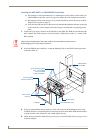
Verify that the terminal end of the power cable is not connected to a power source
before plugging in the 2-pin power connector.