


6
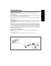
Electrical Connections and Installation
@/<?#&*>@! To avoid the aggravation of costly mistakes and serious damage that could make
you feel this way, please carefully read all of the instructions before you begin. Carefully follow all
instructions. You’ll be glad you did!
GENERAL RECOMMENDATIONS
• If you’re not confident that you can install the unit correctly, have it installed by a qualified
Blaupunkt installation technician.
• Use this unit only with negative ground 12 Volt (11-16 Volt) direct current (DC).
• Be sure to detach the faceplate before you start to connect or install the unit.
• Don’t assume that a seemingly matching wire harness in the vehicle has leads that match the
leads of the unit’s wire harness.
• We recommend making and testing all electrical connections before installing the unit. Connect
the leads (wires) according to instructions and diagram below.
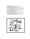
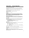
ELECTRICAL CONNECTION INSTRUCTIONS
1. Disconnect the vehicle battery’s negative terminal before making connections.
2. Connect the speakers and/or external amplifiers (if you have any) following the guidelines in
the SPEAKER CONNECTION section below.
3. Connect the blue (trigger output) lead to an antenna motor trigger switch input terminal (if you
have one). (Maximum amperage required must not exceed 150mA.)
4. If you have an external amplifier, connect the blue/white lead to the amplifier’s trigger switch
terminal. DO NOT connect the blue/white lead to the antenna’s power supply input. (Maximum
amperage required must not exceed 150mA.)
5. If you have a cellular telephone set that has a mute lead (lead that supplies constant ground
when telephone is in use), connect it to the dark green lead.
6. Connect the black (power ground) lead to a grounded metal part on the vehicle. We
recommend grounding all audio system black ground leads (receiver, external amplifier, etc.)
to a common grounding point, preferably a non-painted surface under the instrument panel.
7. Connect the yellow (constant power) input lead to a source of constant battery power,
preferably a terminal to an appropriate slot in the fuse box.
8. Connect the red (turn-on power) input lead only after the other leads are connected. Be sure to
connect the red lead to a positive (+) 12 Volt power terminal that is energized only when the
ignition key is set to the on position or accessory position.
9. Cover the ends of any unused leads with electrical tape. This will prevent them from touching
the vehicle or each other and causing a short-circuit and damage to the unit or vehicle.
10. Reconnect the vehicle’s battery.
11. Verify that no fuses have blown.
12. Plug the harness into the unit.
13. Attach the faceplate and test the unit.
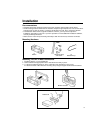
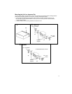
Once the connections have been successfully made, you can begin to mount the unit.
SPEAKER CONNECTIONS
The unit’s Dual-Level Fader allows you to fade between the front and the rear channels using
either the front and/or rear speaker leads and/or the rear preamp outputs, providing you
tremendous flexibility in configuring your speaker arrangement:
• You can connect a speaker (regular, co-axial or tri-axial speakers or component speaker system,
all hereafter referred to simply as “speaker”) to each of the units’ four pairs of speaker leads.
• You can connect the 2 RCA preamp outputs to multiple external amplifiers and power multiple
speakers or speaker systems through the amplifiers. (Blaupunkt amplifiers and speakers
available separately). To add front preamp output, purchase Blaupunkt part 8634494218, which
is included in the CDC-A05 and CDC-A071 changers’ harnesses.
• You can use a either or both of these two methods.