


Page 4 of 12 Installation and Operating Instructions SC-411RD-10
7/30/12 CP5094C
INSTALLATION
Proper installation of the unit is essential for years of safe, reliable operation. Please read all instruction before
installing the unit. Failure to follow these instructions can cause serious damage to the unit or vehicle and may
void warranties.
SAFETY PRECAUTIONS
For the safety of the installer, vehicle operator, passengers and the community please observe the following
safety precautions. Failure to follow all safety precautions and instructions may result in property dam-
age, injury or death.
Qualifications - The installer must have a firm knowledge of basic electricity, vehicle electrical systems and
emergency equipment.
Mounting - Mount the control head for easy access by the vehicle operator. DO NOT mount in air bag deploy-
ment area. Assure clearances before drilling in vehicle. Mount the amplifier in a protected area with at least 1”
clearance on all sides for heat dissipation.
Wiring - Use wiring capable of handling the current required. Make sure all connections are tight. Route wiring
to prevent wear, overheating and interference with air bag deployment. Install and check all wiring before con-
nection to vehicle battery.
Testing - Test all siren functions after installation to assure proper operation. Test vehicle operation to assure
no damage to vehicle.
Keep These Instructions - Keep these instructions in the vehicle or other safe place for future reference.
Advise the vehicle operator of the location.
UNPACKING
Inspect contents for shipping damage. If found alert carrier immediately. Contents should include control
head with attached microphone, amplifier, (2) mounting brackets with screws, microphone bracket with screws,
legend sheet, (3) connectors, 25ft CAT 5e interconnect cable and these instructions. Contact supplier immedi-
ately if any components are missing.
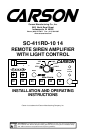
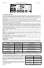
MOUNTING - Control Head
Choose a mounting location convenient to the operator and away from any air bag deployment areas. Inspect
behind mounting area for clearance. Consider wire routing and microphone bracket placement. Connect inter-
face cable prior to mounting.
The control head can be surface, flush or bracket mounted using the supplied brackets and hardware. If longer
fasteners are used assure that screws do not enter rear of unit more than 3/8".
MOUNTING - Amplifier
Choose a mounting location that will assure at least 1” clearance on all sides with adequate ventilation to pre-
vent overheating. Inspect behind mounting area for clearance. Consider wire routing and access to connec-
tions. Make all wiring connections prior to mounting.
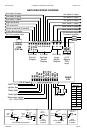
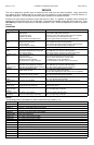
ELECTRICAL CONNECTIONS - Amplifier
Electrical connections to the unit are made using removable terminal blocks and screw terminals. Labels on the
unit identifies each terminal function. A CAT-5e cable connects between the control head and the amplifier. If
the unit needs service the plugs can be easily removed without unwiring. Connect all wires prior to applying
power to the unit and prior to final mounting. Attach leads by stripping 3/8", inserting into plug and clamp by
tightening screw. Make sure the screw is tight and the wire can't be pulled out. Failure to adequately tighten
the screw can result in improper operation or burning the connector and wire.
POWER Input - This is like a power switch for the entire unit. Connect to a positive circuit controlled by the
vehicle ignition switch, usually a terminal at the vehicle fuse panel.
OPTIONAL CONNECTIONS - Amplifier
SIRCTRL Input - This input allows activation by an external source of either the Horn or other function.
Settable for +12 (default) or ground activation.
LITCTRL Input - This input allows cycling by an external source through the lever switch positions. Settable for
+12 (default) or ground activation.
CUTOUT Input - The Cutout Input turns off any siren tone output when activated, and remains off until a control
is activated or changed. Settable for +12 (default) or ground activation.
RADIO Input - Connect to radio output terminals or its speaker. The Radio Volume control is on the amplifier
and is a one time setting depending on the radio connected.
VIDEO Output - A video camera trigger output is activated high (+12) with the lever switch or programmed
auxiliary switches. See OPTION SETTINGS section.
LFT-A, RGT-A, CTR-A Outputs - These 3 active high (+12) outputs are available for arrow stick control.
LFT-A, RGT-A AND CTR-A outputs are active when center selected.
Sound Hazard - Sound level from siren speaker (>120dBA @ 10 feet) may cause hearing damage.
Do not operate siren without adequate hearing protection for you and anyone in immediate vicinity.
(Ref. OSHA 1910.95 for occupational noise exposure guidelines)