


SC-411RD-10 Installation and Operating Instructions Page 5 of 12
CP5094C 7/30/12
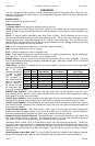
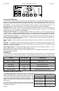
-VDC
switching
example
ADDED DOOR
SWITCH
CUT
+VDC Switching
example
DOOR
SWITCH
+VDC
CUT
SPLICE
DOME
LIGHT
S6
S5
S4
S3
S2
S1
RGT-A
LFT-A
CTR-A
VIDEO
L3
L2
L1
SERIAL
COM
(CAT-5e)
SPKR1
SPKRC
SPKR2
CUTOUT
SIRCTRL
LITCTRL
BACKLIT
RADIO
RADIO
POWER
GND
GND
RADIO
VOL
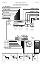
3-Pin Block
Aux switch 3 output
Aux switch 2 output
Aux switch 1 output
Right arrow stick
Left arrow stick
Center arrow stick (if needed)
Video camera trigger
CAT-5e interface cable
0.2 A max
Control
Outputs
10 A max
Auxiliary
Switch
Outputs
20 A max
Lever
Switch
Outputs
50 A max
+12 V
Battery
POS
Input
Aux switch 4 output
Aux switch 5 output
Aux switch 6 output
Lever switch 1 output
Lever switch 2 output
Lever switch 3 output
(2) 50A fused inputs
(customer supplied)
50A brkr
50A brkr
+ +
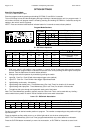
Recommended
Wire Size
Amps Size
5 - 10 #16
10 - 15 #14
15 - 25 #12
25 - 40 #10
40 - 60 #8
60 - 80 #6
Use next larger size
if longer than 10 ft.
1 - 5 #18
<1 #22
(5 A / spkr)
(10 A / lead)
BATT NEG
Ignition Aux
Radio Spkr
Dash lights
Momentary switch
(to +12 or GND)
AMPLIFIER WIRING DIAGRAM
+VDC Switching examples
HORN
RING
SWITCH
+VDC
SIRCTRL
SPLICE
HORN
RING
SWITCH
+VDC
Added
SPDT
Switch
HORN
HORN
-VDC
switching
example
MOMENTARY
FOOT
SWITCH
AUX
SIRCTRL
10-Pin Terminal Block
12-Pin Terminal Block