


SC-411RD-10 Installation and Operating Instructions Page 9 of 12
CP5094C 7/30/12
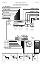
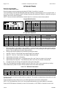
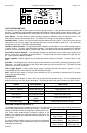
LIGHT SYSTEM CONTROLS
A 4-position lever switch provides control of primary lighting functions. It also provides automatic activation of
the siren. Six additional programmable pushbuttons provided for auxiliary lighting or other device control. Two
dedicated switches operate directional control lights (“Arrow Stick”), with flashing indicators on the control panel.
Lever Switch - The lever switch by default provides progressive (additive) control of lighting functions. The
third position also provides Automatic Siren. The installer can change to non-progressive operation.
Automatic Siren - Position 3 of the lever switch provides Automatic Siren control. If the siren controls are set
where there is no siren tone output, the Automatic Siren will override with Wail or other tone. The cutout input
will stop the siren tone. This feature may be disabled.
Auxiliary Control Switches - Six lighted pushbutton switches are provided for various other lighting functions
or device control. The switch lights Red when activated. The switches may also be programmed for different
functions, and these switches may be combined with each lever switch position to automatically turn on and off.
Arrow Stick Control Switches - Two dedicated switches are provided to control traffic director lights on the
vehicle. Press left or right buttons to set the direction. Turning on both will set the output to left, right and cen-
ter. Lights show the operation selected.
Switch Legends - Different legends may be selected to match the device controlled. A sheet of labels is sup-
plied.
OUT/DIM - The backlighting and indicator lights can be dimmed or turned off by repeatedly pressing the OUT/
DIM button. An optional connection to the vehicle dash lights may also control this level. This button will light
whenever a siren tone is produced.
Video Trigger Output - A video camera trigger output is activated with the lever switch in position 1, 2, or 3.
Programmed auxiliary control switches may also activate the output.
Alert - While the lever switch or auxiliary control switches are on, an alert beep is sounded every 15 seconds.
This can be optionally disable.
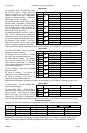
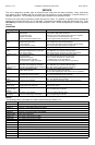
DIAGNOSTICS
The unit monitors all outputs for faults, which are usually traced to shorted circuits. The unit indicates these
faults by flashing one or more lights and beeping. The following table shows fault indications and likely causes.
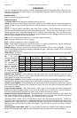
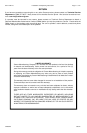
PROGRAM TRANSFER (QuickClone™)
To facilitate programming of multiple vehicles this unit automatically synchronizes option settings between the
control head and amplifier on power-up as shown. Transfer the
settings to multiple vehicles by temporarily installing with a com-
mon control head, power-up/down (transferring options to the
amplifier), then permanently install the supplied control head. On
power-up the options are transferred from the amplifier to the
control head.
If a control head or amplifier is sent in for service it will be set to
default prior to return, and will automatically synchronize with the
mating part on power-up.
Control Fault Indication Likely Cause
Lever Switch light 1, 2 or 3 1, 2 or 3 flashes Blown fuse at 1, 2 or 3
Switch 1 - Switch 6 Switch light flashes Blown fuse at S1 - S6
Arrow Stick Switch Switch light flashes LFT-A, RGT-A or CTR-A output shorted (auto-reset)
Siren output 1 OUT/DIM light flashes Blown fuse at siren CH1
Siren output 2
OUT/DIM light double
flashes
Blown fuse at siren CH2
Both siren outputs
OUT/DIM light triple
flashes
Blown fuses at siren CH1 & CH2
Option Settings Action
Head = Amp Normal power-up
Head ≠ Default and
Amp ≠ Default
Head transferred to
Amp, power-up
Amp = Default and
Head ≠ Default
Head transferred to
Amp, power-up
Amp ≠ Default and
Head = Default
Amp transferred to
Head, power-up
S1
S2
S3
S4
S5
S6
OFF
1
2
3
PA VOL
WARNING: WEAR HEARING PRO TECTION REF. OSHA 1910.95
YELP
WAIL
STBY
PHSR
CYCLE
RADIO
CARSON
SC
SCSC
SC
-
--
-
411
411411
411
Elite
Force
OUT/DIM
MANUAL
HORN