


page 14
CDi Series Power Amplifiers
Operation Manual
4 Advanced Features and Options
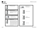
Figure 4.1
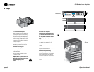
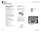
DC Protection
NOTE: For detailed information about these Crown
amplifier features, please consult the Crown
Amplifier Application Guide, available on the Crown
website at www.crownaudio.com.
4.1 Protection Systems
Your Crown amplifier provides extensive protection and
diagnostic capabilities, including output current limiting,
microprocessor-controlled DC protection, and special
thermal protection for the unit’s transformers and output
devices.
4.1.1 Output Current Limiting
Output Current Limiting circuitry protects the amplifier
output stage from damage caused by short-circuit loads.
4.1.2 DC Protection
DC Protection shuts down the amplifier in the event of an
output DC offset exceeding 2V. In the majority of cases, DC
protection is indicative of a faulty amplifier channel, and will
be accompanied by an illuminated red Clip LED, even with
no input connected and level controls set at minimum
(Figure 4.1). If this is the case, contact your dealer or
service center.
4.1.3 Thermal Protection
The Thermal Protection circuit will activate if the internal
heatsink temperature exceeds proper operating
tempera tures (176°F, 80°C). When the heatsink
temperature has fallen to a safe level, this protection circuit
will automati cally be reset. Principal causes of thermal
protection are:
1) Inadequate ventilation of the equipment rack
2) Incorrect load impedance
3) Output cable short circuit
4) Blocked air vent
5) Heatsinks in need of cleaning
6) Cooling fan failure.
The cause of your amplifier’s thermal protection state
should be determined and corrected as soon as possible.
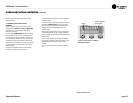
4.1.4 Non-Touch Cover
Located over the amplifier output terminals, this included
accessory provides a shock-proof cover for the output
ter minals.
1. Remove the screw holding the cover onto the amplifier
back panel, and remove the cover. Keep the screw.
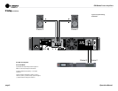
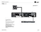
2. The cover has two tabs A and B (Figure 4.2). Insert tab
A into the slot just to the left of the output terminals
(Fig ure 4.3).
3. Put the screw through tab B, and screw it into the hole
just to the right of the output terminals (Figure 4.3).
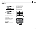
4.1.5 Attenuator Security Covers
The included attenuator security covers (Figure 4.4) can
replace the existing level-control knobs so that the
ampli fier output level cannot be changed. The knobs
snap into the front panel.
Tab A
Tab B
Non-touch cover
Figure 4.2 Interior of Non-Touch Cover
Tab A
Tab B
Non-touch cover
Figure 4.3 Cover Placement
Over Output Terminals
Figure 4.4 Attenuator Security
Cover