page 8
CDi Series Power Amplifiers
Operation Manual
Channel 2
Channel 2
Channel 1
Channel 1
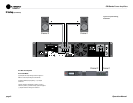
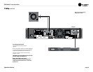
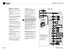
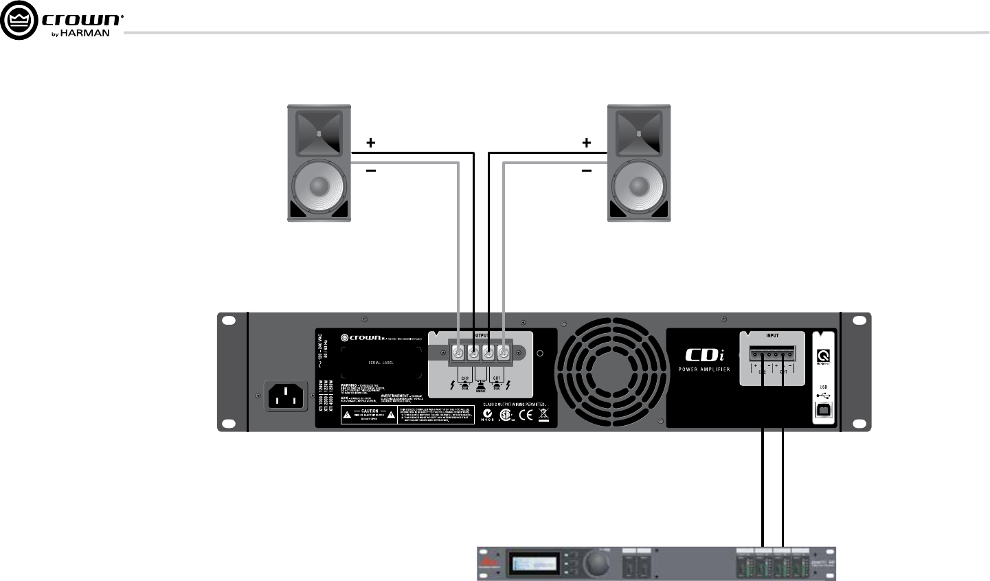
Figure 2.5 System Wiring,
Dual Mode
2 Setup (continued)
2.6 Wire Your System
2.6.1 Dual Mode
Typical input and output wiring is shown in Figure 2.5.
INPUTS: Connect input wiring for both channels.
OUTPUTS: Maintain proper polarity (+/–) on output
connectors.
Connect Channel 1 loudspeaker’s positive (+) lead to
Channel 1 positive (+) terminal of amp; repeat for negative
(–). Repeat Channel 2 wiring as for Channel 1.


