Dayton Operating Instructions and Parts Manual
11
Model 4E769B
Version B - For Reduction G016.J
®
Dayton Operating Instructions and Parts Manual
4E769B
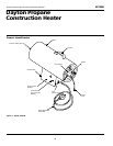
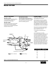
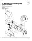
Replacement Parts List
Reference
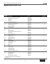
Number Description Part No. Quantity
1 Inner shell (Combustion Chamber) 099568-01 1
2 #10-16 x 3/8" Hex tap screw *M11084-26 7
3 Outer shell 099599-01AZ 1
4 Handle M51104-01 1
5 Hex tap shoulder screw 099230-01 4
6 #10-16 x 3/4" Hex tap screw *M11084-29 2
7 #12-14 x 1/2" Hex tap screw *M11084-3 3
8 Thermocouple clip 099237-01 1
9 Burner assembly 099727-01 1
10 Electrode ignitor 099539-01 1
11 #8-18 x 3/8" Hex tap screw *M11084-38 1
12 Fan 099537-01 1
13 Motor assembly 099521-01 1
(Includes rubber washer and fan nut)
14 Fan guard 099540-01 1
15 Captive washer nut 097384-02 3
16 #4-40 x 1/2" Hex screw *097968-05 2
17 #4-40 Hex nut *NPC-00C 2
18 Thermal switch kit 101732-02 1
19 Universal bushing 097776-01 1
20 Wire clip 099542-01 1
21 Thermocouple 099538-01 1
22 Valve/orifice assembly 099728-01 1
23 Piezo ignitor 102445-01 1
24 Sleeve cap 078978-03 1
25 Base 103892-01 1
26 #4 Lock washer *100397-01 4
27 1/8" Steel rivet *099202-02 1
∆ Tradename decal 100163-03 1
∆ Tradename decal 100163-04 1
∆ General information decal 099548-05 1
∆ Operation decal 099666-01 1
∆ LP Warning decal 079663-01 1
∆ Notice decal 099672-01 1
∆ Hose/regulator assembly LPA3090 1
(*) Standard hardware item, available locally.
(∆) Not shown.


