


33
Note: Functioning changes in the models DPA 4120 (starting with serial numbers: 100 11) and DPA 4140 (starting
with serial numbers: 100 11) in association with the input module NRS 90225: To achieve reliable attenuation
of switching noise (knacks), the monitor output stays muted as long as the READY-relay is not pulled.
Because of circuit design reasons this causes that the monitor output is also muted even when a ground-fault
appears at the main output.
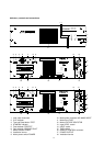
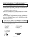
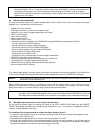
8.2 Remote module NRS 90222
This input and remote module for the power amplifiers DPA 4120 and DPA 4140 is meant for insertion at the power
amplifiers' rear. It provides the following functions:
• lockable XLR input connector
• XLR output connector; to patch the input signal through
• input level; can be set via a programmable audio level control
• MUTE (via level control)
• mains remote ON/OFF
• battery remote ON/OFF
• control of the D- and E-relays
• surveillance and fault messaging via the PROMATRIX manager DPM 4000 corresponding to IEC 849
- thermal overload of the mains transformer
- thermal overload of the power amplification stage
- ground fault (optional; only with installed NRS 90224)
- pilot tone signal (optional; only with installed NRS 90224)
- measurement of the output voltage / level
- measurement of the output current
- surveillance of the connected loads via current/voltage measurement
• MONITOR output; electronically balanced
• monitoring: input/output signals can be assigned to the monitor bus
• input transformer for floating, balanced input (optional)
• output transformer for floating, balanced monitor output (optional)
• pilot tone signal ON/OFF (optional)
The remote module allows to remotely control and monitor the operation of the power amplifiers DPA 4120 and DPA
4140 from the PROMATRIX manager DPM 4000 (for further details please refer to the PROMATRIX handbook).
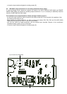
Caution: Before installing the input module NRS 90222, you have to unplug the mains connector as well as a
presumably connected battery cord.
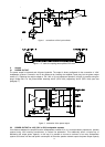
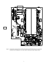
Before installing the input module, it is necessary to remove the two locking screws B on the rear panel of the
appliance. For installation the printed board assembly first has to be inserted into the guiding rails. After carefully
pushing the module in it has to be locked by using the two screws mentioned before.
Note After installing the remote module NRS 90222 it is necessary to set its address according to the
description in the PROMATRIX handbook using the two "HEX-code switches" ADDRESS (21) and note
the setting within the field ADDRESS on the rear panel of the appliance using a waterproof marker pen.
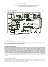
8.3 NRS 90208 input transformer for the floating, balanced input
For the case that floating inputs are required, the inputs of the INPUT MODULE NRS 90225 and the REMOTE
MODULE NRS 90222 are prepared for retrofitting input transformers. If so, it is necessary to additionally install the
extension kit NRS 90208 per each input.
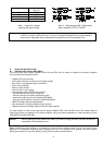
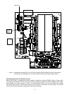
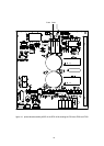
The installation has to be performed as follows (see figure 6 and/or figure 7):
- to remove the input module you have to loosen the two locking screws (B) on the rear panel of the appliance. Now,
the module can be easily torn out.
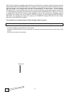
- before installing the input transformer you have to remove the resistors R1 and R2.
- mount the input transformer onto the printed board assembly, so that the marking located on the connector side of
the transformer matches with the one on the printed board assembly. To prevent short-circuits place the supplied
insulation disc between the transformer and the printed board assembly.