


30
of 200W (connection impedance 50 ohms) with the DPA 4120, respectively 400W (connection impedance 25 ohms)
with the DPA 4140. Connection is performed using the 100V output (17) (see also figure 3). In a few special cases it
is also possible to operate the loudspeaker systems with 70V or 50V output voltage (see also paragraph 7).
Caution It is possible that during operation shock-hazard output voltages can be present at the POWER
OUTPUT connector (>34V peak value). Thus, the connected loudspeaker groups have to be installed in
accordance to applicable security standards and regulations (see also paragraph 8.5.2).
5.3 SINGLE CALL and obligatory reception relays OVERRIDE BYPASS
Combined with the PROMATRIX manager DPM 4000 or other external controls it is also possible to transmit single or
collective calls with obligatory reception; i. e. bridging of possibly existing volume controls of the loudspeaker
systems. For details on how to connect the outputs, please refer to figure 3; for the connection of relays, please refer
to paragraph 5.6 respectively the PROMATRIX handbook.
5.4 POWER OUTPUT for low impedance loudspeaker systems
Switching the output to 4 ohms allows the connection of low impedance loudspeaker systems (4-16 ohms) (see also
paragraph 7 and figure 3). Because of the occurring line attenuation, the distance between amplifier and loudspeaker
system should not exceed 50m. Please make sure that the overall loudspeaker impedance does not decline a value
of 4 ohms and that the stated power handling capacity of a single speaker system is not exceeded.
5.5 MONITOR output
The MONITOR output (16) on the NRS 90225 allows the connection of an additional power amplifier for monitoring
purposes. The low impedance output is electronically balanced, which offers the possibility to achieve cable lengths of
up to 200 m. Connection is performed via the REMOTE CONTROL pin-connector strip (see also figure 4). For the
remote control module NRS 90222, the MONITOR output is located on the REMOTE CONTROL connector (22). The
PROMATRIX manager DPM 4000 switches the signal to the according the monitor channel. In case a floating output
is required, the monitor output is prepared for retrofitting an output transformer; provided through the optional extension
NRS 90227 (please also refer to paragraph 8.4).
Note: Functioning changes in the models DPA 4120 (starting with serial numbers: 100 11) and DPA 4140 (starting
with serial numbers: 100 11) in association with the input module NRS 90225: To achieve reliable attenuation
of switching noise (knacks), the monitor output stays muted as long as the READY-relay is not pulled.
Because of circuit design reasons this causes that the monitor output is also muted even when a ground-fault
appears at the main output.
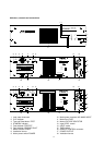
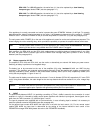
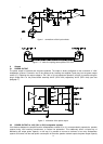
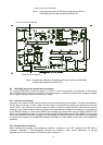
5.6 REMOTE CONTROL connector (only NRS 90225)
The 15-pole sub-D REMOTE CONTROL pin-connector strip (16) provides several different control in-/outputs:
- Ground of the stand-by power supply - negative pole grounded
- POWER REMOTE - via contact to ground potential
- BATTERY REMOTE - via contact to ground potential
- MONITOR output - electronically balanced
- READY-message - with floating contact
- Obligatory reception relay D-RELAY - via contact to ground potential
- Single call E-RELAY - via contact to ground potential
2 ⊥ STANDBY GROUND
3 POWER REMOTE
4 BATTERY REMOTE
5 D - RELAY
6 E - RELAY
7
8 READY
15
9 + MONITOR
10 - MONITOR
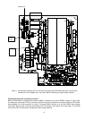
figure 4 connections on the REMOTE CONTROL pin-connector strip
6. Indicators
REMOTE CONTROL