


26
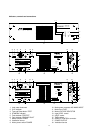
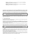
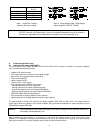
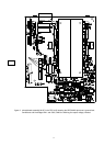
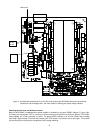
19 CIRCUIT ⊥ TO CHASSIS SWITCH
20 DC INPUT 24V = (battery)
21 IDENT ADDRESS switch
22 REMOTE CONTROL connectors
23 STATUS indicator
A locking screws power supply printed board
B locking screws INPUT MODULE
Contents
Performance Features.........................................................................................................................23
Indicators, controls and connections ....................................................................................................25
1. Utilization .........................................................................................................................................27
2. Installation ........................................................................................................................................27
3. Before the first operation .....................................................................................................................27
3.1 Mains operation ..........................................................................................................................27
3.2 Battery operation 24V DC.............................................................................................................28
4. INPUT...............................................................................................................................................28
5. Outputs.............................................................................................................................................29
5.1 POWER OUTPUT........................................................................................................................29
5.2 POWER OUTPUT for 100V (70V or 50V) loudspeaker systems........................................................29
5.3 SINGLE CALL and obligatory reception relays OVERRIDE BYPASS................................................29
5.4 POWER OUTPUT for low impedance loudspeaker systems.............................................................29
5.5 MONITOR output .........................................................................................................................30
5.6 REMOTE CONTROL connector (only NRS 90225) ..........................................................................30
6. Indicators ..........................................................................................................................................30
6.1 STANDBY indicator......................................................................................................................30
6.2 READY indicator..........................................................................................................................30
6.3 PROTECT indicator......................................................................................................................30
6.4 GROUND FAULT indicator............................................................................................................30
6.5 Aussteuerungskontrolle und CLIP-Anzeige.....................................................................................31
7. Switching the output voltage................................................................................................................31
8. Enhanced application field...................................................................................................................32
8.1 General input module NRS 90225..................................................................................................32
8.2 Remote module NRS 90222..........................................................................................................32
8.3 NRS 90208 input transformer for the floating, balanced input ............................................................33
8.4 NRS 90227 output transformer for the floating, balanced monitor output ............................................33
8.5 NRS 90224 pilot tone and ground fault surveillance..........................................................................35
8.5.1 Pilot tone surveillance..........................................................................................................35
8.5.2 Ground fault surveillance......................................................................................................35
9. 19"-case and 19“-rack shelf system installation.....................................................................................38
10. Ground lift switch CIRCUIT ⊥TO CHASSIS SWITCH..............................................................................38
11. Fuses................................................................................................................................................38
11.1 Fuses in the DPA.......................................................................................................................38
11.2 Fuses in the DPA.......................................................................................................................38
12. Power amplifier specifications..............................................................................................................42
12.1 DPA 4120 power amplifier 200 W.................................................................................................42
12.2 DPA 4140 power amplifier 400 W.................................................................................................43
13. Extension specifications .....................................................................................................................44
13.1 NRS 90225 general input module.................................................................................................44
13.2 NRS 90222 remote module .........................................................................................................44
13.3 NRS 90208 input transformer for floating, balanced input................................................................44
13.4 NRS 90227 output transformer for floating, balanced monitor output ................................................44
13.5 NRS 90224 pilot tone and ground fault surveillance........................................................................44
14. Block diagrams..................................................................................................................................67
14.1 Power amplifiers DPA 4120 / DPA 4140........................................................................................67
14.2 NRS 90225 general input module.................................................................................................68