


31
6.1 STANDBY indicator
When the appliance is correctly connected and mains and/or battery power is present, the green STANDBY indicator
(4) will light.
6.2 READY indicator
Both amplifiers, the DPA 4120 and the DPA 4140, employ power-on switching delays of approximately 3 sec. to
effectively eliminate power-on switching noise. After this time, the green READY indicator (7) lights and the READY
fault message relay picks up when no error is being detected. When the power amplifier's mains transformer exceeds
a certain value or, when – with installed NRS 90224 extension – the pilot tone falls below the threshold (see also
paragraph 8.5.1), the green READY indicator (7) is not lit and the READY fault message relay drops.
6.3 PROTECT indicator
When thermal overload of the mains transformer or the power amplification stage is encountered, the red PROTECT
indicator (5) will light and the READY fault message relay drops. After the amplifier regained normal temperature, the
red PROTECT indicator (5) is automatically dimmed and the appliance returns to normal operation. High temperature
can be caused by overload, extreme ambient temperatures or faulty functioning of the system's ventilation.
6.4 GROUND FAULT indicator
If, with the NRS 90224 extension installed, a ground fault is being detected at the power output, the red GROUND
FAULT indicator (6) will light and the READY fault message relay will drop. During the occurrence of this error normal
operation is maintained. After eliminating the cause for the ground fault, pressing the TEST button (3) resets the
GROUND FAULT indicator (6) (see also paragraph 8.5.2).
6.5 Level meter and CLIP indicator
The green LED-indicators -13dB and 0dB (1) together with the red CLIP-LED (2) allow to monitor the output level,
effectively avoiding overdrive conditions that lead to distortion and overload at the power outputs which could damage
the connected loudspeaker systems.
- If the red CLIP-LED (2) shortly lights during program peaks, maximum non-distorted modulation is achieved.
- Continuous lighting or blinking of the red CLIP-LED (2) signals overdrive. In this case the input level has to be
reduced.
- If the green LED indicator (1) does not light or is only briefly lit with the red CLIP-LED blinking at the same time, this
signals the encountering of an overload or short-circuit condition at the output. In this case the impedance of the
connected load has to be checked.
Caution During normal operation the red CLIP-LED should only light briefly and shortly!
7. Switching the output voltage (only to be performed by a qualified service technician!)
The DPA 4120 and DPA 4140 amplifiers allow the connection of 50V, 70V, 100V or low-impedance loudspeaker
systems (4 ohms). They are factory-preset to an output voltage of 100 V. Switching the output voltage to 4 ohms, 50V
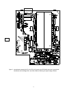
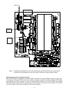
or 70V can be performed by changing the bridge B411 on the power amplifier printed board assembly 84187 (DPA
4120) or 84175 (DPA 4140):
Caution Before opening the appliance, make sure to disconnect the mains and/or battery power source!
- To open the appliance, the top panel has to be removed.
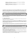
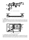
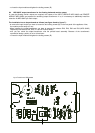
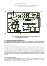
- The bridge B411 (yellow wire) has to be removed from the contact B407 and re-attached to the desired contact (see
table 1) (see also figure 8 respectively figure 9).
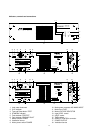
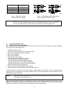
- he coding-bridges S405 and S406 for the output recognition have to be inserted according to the illustration in figure
5.
(the inserted coding-bridge is marked in black)
- The top panel has to be re-attached.
Note By using a waterproof marker pen and after switching the output voltage, the newly set value
has to be marked in the filed "OUTPUT VOLTAGE" on the rear panel of the appliance.