


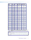
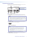
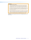
Transmitter Rear Panel Features
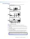
Figure 3 shows an MTP T 15HD A transmitter, which has all of the connectors and other
features that are on either transmitter in the MTP 15HD A series.
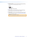
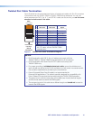
MTP T 15HD A Transmitter
OUTPUT
INPUT
AUDIO
POWER
12V
.5A MAX
MONITOR
PRE-PEAK
ON
OFF
MTP T 15HD A
NOTE: A “C7” label is affixed to
transmitters designed for
STP201 or CAT 7 cable.
1
2
5 63
4
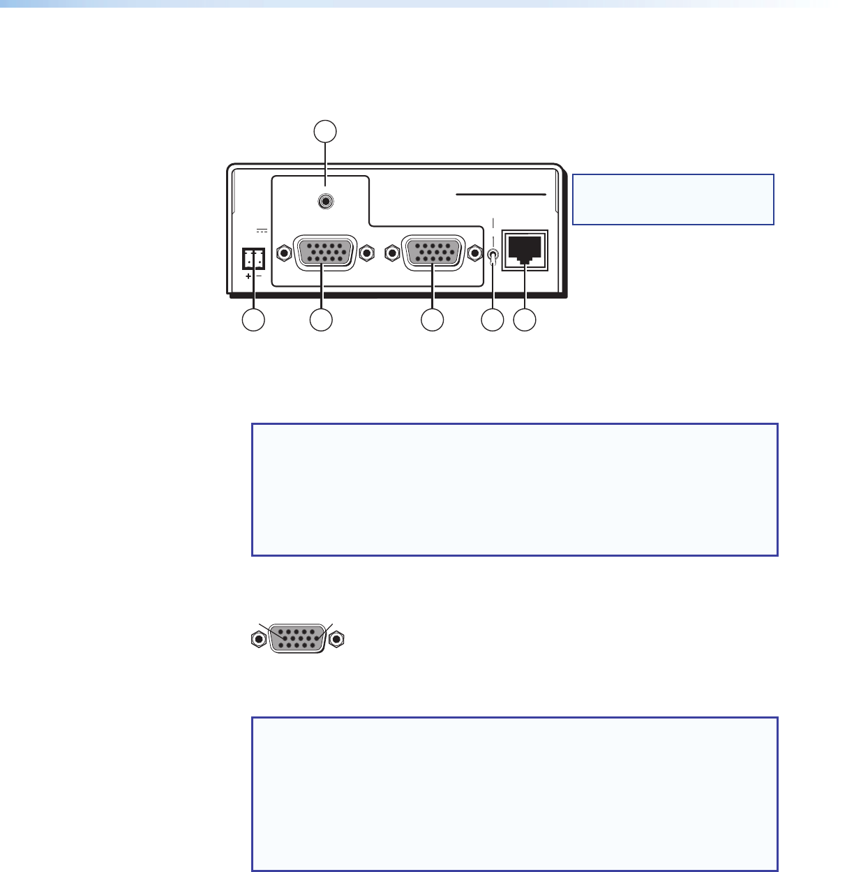
Figure 3. Transmitter Rear Panel
a
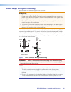
Power connector — Plug the included external 12 VDC power supply into this
2-pole captive screw connector (see Power Supply Wiring on page 12 to wire the
connector).
NOTES:
• The length of the exposed wires in the stripping process is critical. The ideal
length is 3/16 inches (5 mm). If the exposed section is longer, the exposed wires
may touch, causing a short circuit between them. If it is shorter, the wires can be
easily pulled out, even if tightly fastened by the captive screws.
• Do not tin the wires. Tinned wire does not hold its shape and can become loose
over time.
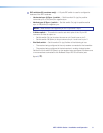
b
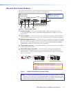
Input video connector — Connect a computer video source to this 15-pin HD
connector for high resolution video input (see figure 4).
51
15 11
610
Female
Figure 4. 15-pin HD Connector
NOTES:
• Input only sync signals (no video signals) on the sync pins (13 and 14).
• For component video, use the R (R-Y) and R return pins (pins 1 and 6),
G (Y) and G return pins (pins 2 and 7), and B (B-Y) and B return pins
(pins 3 and 8). For S-video, use the R, R return (C-chroma), G, and
G return (Y-luma) pins.
• For composite video, use the G pin and the associated return pin. For additional
genlocked video signals, use the R, B, and associated return pins.
c
Monitor connector — Connect a video monitor to this 15-pin HD connector for
buffered, high resolution video loop-through.
MTP 15HD A Series • Installation and Operation 9