


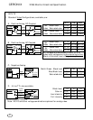
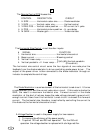
The Horizontal Size Control circuit has four inputs:
Q
13
R
S
1. H SIZE ----------- Horizontal raster size --------- Diode modulator
2. V SIZE ----------- Vertical raster size ------------- Vertical control
3. V RAS. POS. --- Vertical raster position ------- DC current to V. yoke
4. H POS ------------ Horizontal picture position -- H. sync delay
5. M GAIN ---------- Master gain ---------------------- Video interface
The Remote Control PCB houses the:
CONTROL DESCRIPTION CIRCUIT
T
1. To improve the efficiency of the power supply.
2. To permit 120 volt and 230 volt operation. For the 230 volt
operation the voltage doubler is replaced with a bridge rectifier.
A Voltage Doubler is used in the power supply for two reasons:
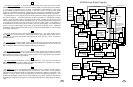
The Diode Modulator is a series element of the horizontal tuned circuit. It forms
a node between GND and the normal yoke return circuit. If this node is shorted to
GND, the result is maximum horizontal size. Forward current in the diode
modulator, at the start of retrace, keeps the node voltage clamped to ground until
enough current flows from the horizontal tuned circuit to exceed this forward
current. The horizontal size, therefore, is controlled by controlling the current to
this diode via the horizontal size control circuit.
The horizontal size control circuit sums the four signals at one node plus the
feedback from the diode modulator to drive a switching mode power driver. The
output of the power driver is then connected to the diode modulator through an
inductor to complete the control loop.
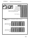
# SIGNAL FUNCTION
1. Horizontal size ------------------------------ Horizontal size control
2. Beam current -------------------------------- Blooming control
3. Vertical linear ramp -----------------------
4. Vertical parabolic + V. linear ramp ---
(#4)-(#3)=Vertical parabolic
(Pincushion)
}