


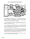
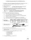
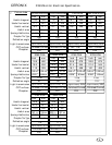
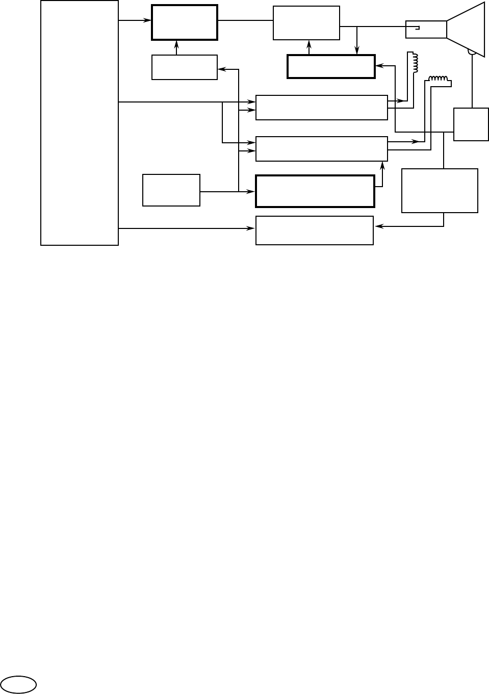
Monitor Simplified Block Diagram.
This block diagram gives a broad view of the circuit organization of the 1493,
1793, 1993, 2093, 2793, and 3693 monitors. The blocks with the bold outline
represent circuits which provide these monitors with a wide range of
operating conditions without the need for adjustment.
The video interface circuit can be programmed to accept; +Analog AC or
DC coupled, -Analog, and 4 line TTL. The M. GAIN or contrast control is
located on the remote control board.
The auto bias circuit eliminates the need for the color setup procedure.
This circuit is designed to actively compensate for picture tube drift which
normally causes unbalanced color. The auto bias circuit also adjusts the
CRT gain to compensate for gain loss with age.
The horizontal size control circuit permits the horizontal size to be adjusted
from a remote control board. This circuit is also used to compensate for
pincushion distortion and blooming. Anti-blooming is accomplished by
correcting horizontal size variations which are caused by the additional load
on the flyback transformer under high beam current conditions.
Careful reading of all the information presented in this manual is a good
way to learn how to repair the CERONIX monitor.
1
VIDEO
Output
Drive
Electronics
SYNC
Output
Interface
VIDEO
Blanking
VIDEO
Amps.
AUTO BIAS
Vertical Deflection
Horizontal Deflection
CRT
FBT
Horizontal Size
Control
POWER SUPPLY
Remote
Controls
Isolated
Power
IB
Fault &
High Temp.
Detection