


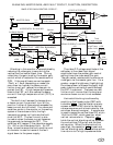
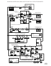
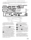
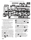
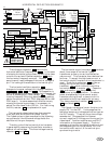
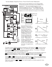
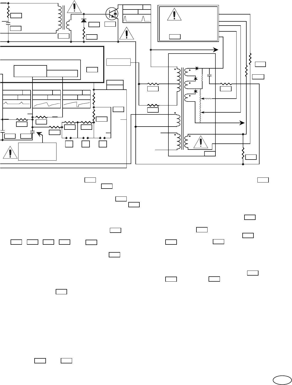
HORIZONTAL DEFLECTION SCHEMATIC.
5.5-6.3V
3.6Vpp 08,E6
Hs3-7VDC
.2Vpp 07,E6
Hs 5-6VDC
7Vpp
Hs
09,E6
+800Hz
680Ω
9 107 8
I10
13
14
15
16
DISCHARGE
HORIZONTAL
OSCILLATOR
H. V+
9.31K
1K
33K
.01uF
I8
I9
345346
415
LA7851
H.Fo ADJ.
17
+200Hz
+400Hz
F
G
340Ω
170Ω
E
I14
I15
I16
10.8-12V
10, E6
Horizontal
Transformer
I11
343
2.2nF
100Ω
19
20
GND
433
2SC5690
434
1.2Ω
435
1N4007
332
2
1
3
4
3,300pF-38KHz
6,800pF-15KHz
3,300pF-31KHz
107V-127V
336
SCREEN
EHT
10
GND
FIL.
FOCUS
1
453
6
8
7
5
4
3
2
FLYBACK
TRANSFORMER
V-
Beam
Current
Fil.
TC11
FOCUS
Screen
EHT
Fil. Rtn.
TC12
467
0Ω
1K
465
9
452
451
452
To Yoke
Drive
Video
Board
800
092
092A
To P/S
The horizontal oscillator capacitor 345
charges to its upper voltage limit through resistors
I10 , I16 , I15 , I 14 , and 336 . This capacitor is
then discharged to the lower voltage limit through the
action of discharge pin 9 and resistor I 9 . The free
running frequency (Hfo) may be adjusted by making
solder connections on the I PRA. (see page 65 for the I
PRA layout). In some cases where there are many
missing horizontal sync pulses, it is necessary to
adjust the Hfo closer than ±200 Hz. For fine tuning
the Hfo, resistor 336 is replaced with a pot.
The duty cycle of the horizontal drive transistor
is generated by comparing the oscillator waveform
against a fixed voltage. This fixed voltage is set by
resistors 417 and 418 .
The voltage on capacitor 346 controls the
horizontal oscillator frequency via I8 . In the case
of missing horizontal sync pulses, the multiplier does
not sink current and flywheel capacitor 344 holds
the horizontal frequency constant. Resistor I7
permits small rapid changes of the control voltage at
pin 7 for locking of the oscillator to horizontal sync.
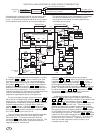
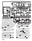
The horizontal phase locked loop then consists
of an oscillator which sets the flyback timing.
The flyback pulse is then compared to the incoming
sync pulse and the difference voltage holds the
oscillator at the sync frequency.
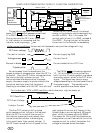
The horizontal output transistor 433 conducts
about three amps of horizontal flyback
transformer primary current and deflection
yoke current. This transistor has a beta as low
as three. To supply the high base current, a
horizontal output transistor drive transformer is
used. The drive transformer 332 builds up
energy during the on time of the drive
transistor, 337 which is the off time of the
horizontal output transistor 433 . Capacitor
343 and resistor I 11 damps the drive
transformer primary waveform. To reduce
power dissipated by the horizontal output
transistor during turnoff, a clamp circuit is
connected to the drive transformer primary.
This clamp consists of resistor 341 , capacitor
338 , and diode 342 .
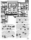
The flyback transformer's main function is to
supply EHT to the CRT. It also supplies the
focus and screen grid voltages which are taps on
the EHT supply. There are three low voltage
secondaries. One supplies the filament
current, negative G1 voltage, and timing on the
video board. Another supplies sync and EHT
information to the power supply. The third
secondary drives the horizontal blanking circuit
and supplies sync for the horizontal PLL, the
horizontal width control, & the vertical sync
synchronizing circuits.
346
I8
344
336
336
345
I7
I9
433
332
343
433
341
417
418
I14I15I10 I16
337
342
338
NO DVM
27,G6
Hs
.9KVpp
I11
83