


1N4148
10
R
VC
4
RED
INPUT
VC
3
GND
B
o
R
o
G
o GAIN
M
+ EN
A
INBGINRIN RR RG
A
- BL
5
VC
G
GREEN
INPUT
6
B
VC
BLUE
INPUT
288
271
278
286
1N4148
270
GND
277
284
1N4148
268
276
4
TTL
BL
B
GND
Controls XRC5346A
RB
241
16 13 5 12396 11
+12V
274
PN2222
275
272
GND
292
281 280 283
21 1415 7 8
0Ω
218
105Ω
270Ω
270Ω
.33uF
311
PN2222
310
.33uF
312
PN2222
308
.33uF
313
PN2222
270Ω
307
303
MPS2907
2.7K
305
MPS2907
237
MPS2907
238 266
MPS2907
1N4937 1N4937 1N4937
88.7Ω 100Ω
319
317
309
47nF
10K
1nF
1N4148
75Ω
75Ω 75Ω
270Ω 270Ω 270Ω
+12V
233
231
232
L
243
242
264
K
225
223
226
J
A5B5
A5
270Ω
315
1N4148
221
10K
070
0Ω
219
PN2222
2.15K
1.87K
2.15K
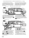
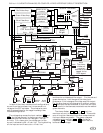
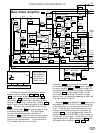
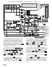
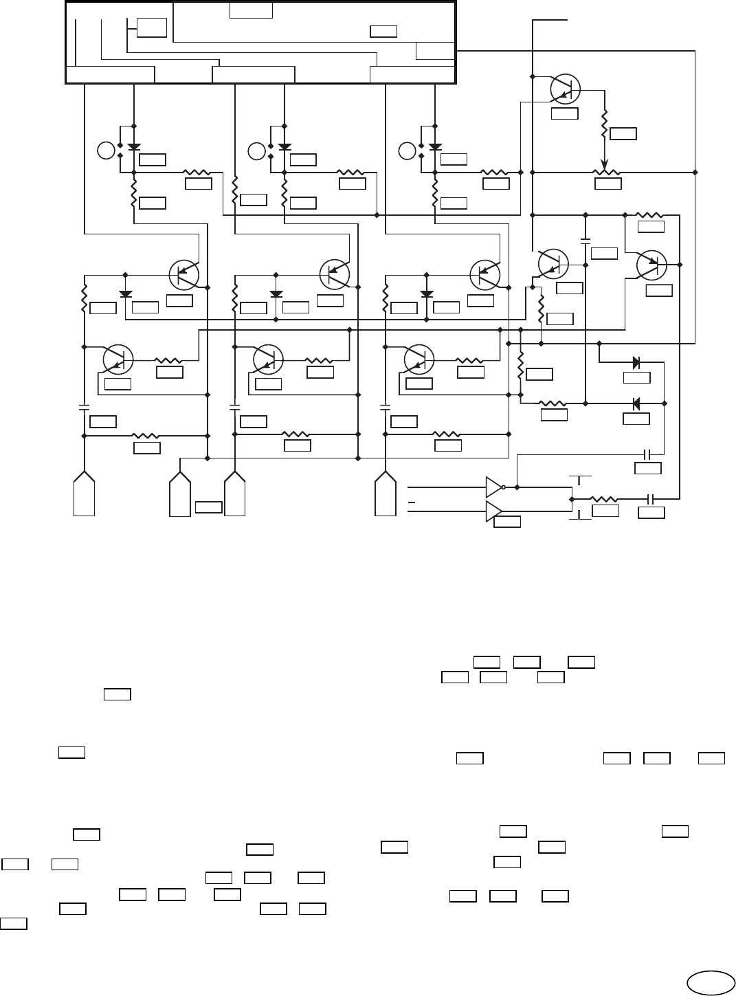
1Vp-p, POSITIVE ANALOG, AC COUPLED, VIDEO INTERFACE CIRCUIT DESCRIPTION.
316
100pF
320
2.7K
2
1
H. Sync.+
H. Sync.
355
320=.30”
320+.45”
+12V
For composite sync.
For separate -H sync
see schematic at DD8.
GND
GND
Black Level
Adjustment
is optional.
273
1.0M
In the + analog AC coupled mode, the video black
level is set by a clamp circuit which is active during the
first part of horizontal sync. For this circuit to work
properly, the incoming video must be at the black level
voltage when horizontal sync starts and remain
blanked for at least 4.5uS.
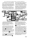
The clamp circuit is dependent on the polarity of
incoming horizontal sync. For separate horizontal
sync, the sync polarity should be positive. For
composite sync, and positive going horizontal sync
pulses, resistor
320 (.30” long) is connected to the
inverting horizontal sync comparator which is the same
as separate, positive, horizontal sync. For composite
sync, with negative going horizontal sync pulses,
resistor
320 (.45” long) makes the connection to the
noninverting vertical sync comparator. This connection
is valid since the horizontal and vertical sync lines are
connected together for composite sync.
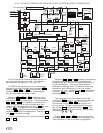
The clamping function is accomplished by turning on
transistor 303 at the start of horizontal sync through
the differentiating action of capacitor 316 and resistors
305 & 320 . The collector of this transistor is
connected to clamp transistors
311 , 312 , & 313
through resistors 310 , 308 , & 307 with pull down
resistor 315 . The coupling capacitors 281 , 280 , &
283 at the video input are set to the black level voltage
by the video source.
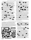
If the coupling capacitor voltage, on the clamped side,
is high at clamp time, the clamp transistor shorts the
capacitor to GND by normal transistor action. If the
coupling capacitor voltage is low at clamp time the
clamp transistors act as dual diodes to raise the
capacitor voltage to GND, which is the black level
reference for the video input circuit.
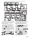
The ground referenced video signal is then buffered
by transistors
237 , 238 , & 266 through protection
resistors 278 , 277 , & 276 . The buffer transistors
are needed to reduce the .6mA bias current, from the
video interface IC, to under 10uA which limits the
coupling capacitor voltage buildup to 2mV during one
horizontal cycle.
Resistor
275 and clamp diodes 271 , 270 , & 268
are connected to the coupling capacitors to limit the
voltage buildup when no sync is present. If this limit
did not exist, the monitor would show excessive
brightness without sync. When sync pulses are
present, capacitor 309 with rectifier diodes 317 &
319 and filter capacitor 272 apply a voltage to the
base of transistor 274 which raises the voltage on the
clamp diodes to avoid interference with the video signal.
Diodes 226 , 243 , & 232 balance the base to
emitter voltage of the buffer transistors. The rest of
the video interface functions the same as the DC
coupled video interface circuit.
303
320
320
315
316
313312311
308
320305
280281
307
283
271
277 276
237 266238
278
272319
309
275 268270
225 243 233
274
317
67
310