


Vertical Osc. O/S, LA7851 pin 16
16H Dly.
1N4148
028
379
PN2222
384
389
0Ω
+12
V
098
383
CS=.45"
Retrace Boost
GND
CS=.74
22K
200K
62K
510Ω
006
0Ω
100A
4
7
100
PN2222
6.8K
099
3
1
2
P
091
4H Dly.
1N4148
025
8H Dly.
1N4148
027
381
15.8K
Autobias
Delay
.1uF
Q1
Vdd
Vss
CD4024
Q2
Q3
Q4
Q5
Q6Q7
KL
NC
CL 12
11
9
6
5
4
1
2
8,10,13
14
7
3
201
200K
101
62K
100
006
1N4148
099
220pF
2H Dly.
1N4148
024
CRT AUTO BIAS
VERTICAL SYNC
+24V
Filament
GND
+12
Hfo=15KHz
For Hfo=25-31KHz
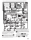
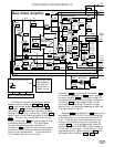
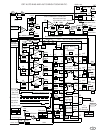
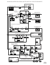
Load resistor 909 eliminates crossover distortion from
the OP Amp.
920 . Resistor 852 and 856 protects the
transistor and OP Amp. from damage due to CRT
arcing.
PNP transistor 928 is used as a voltage translator to
direct the grid pulse from the auto bias IC to G1. The
voltage on G1 is normally -15 to -27 volts depending on
which CRT is used. When the grid pulse at pin 11 is
low, the current from resistor
933 is conducted to
resistor 874 and produces a 10 volt pulse on the minus
G1 line. Capacitor 871 and resistors 855 & 873
protect transistor 928 from CRT arcing.
The auto bias IC (CA3224E) is designed for a supply
voltage of +10V and since the video amplifier requires
+12V, three diodes 903 , 905 , and 906 are used to
supply this IC. Resistors
C4 and C7 form a voltage
divider which supplies the, auto bright, bias voltage to
the LM324
920 . The green and blue channel circuits
are identical to the red channel and are controlled by
the timing logic in the same way.
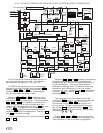
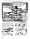
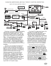
Refer to the waveforms at the bottom left of page 34
for the timing relationship. The vertical retrace boost
pulse, from the LA7838, (15KHz models) or the delayed
vertical sync pulse from the sync delay circuit (25 &
31KHz models) starts the 21 count auto bias state
counter. This pulse is applied to the auto bias IC
through resistor 891 . The negative going flyback
pulse which is used to heat the filament also supplies
the horizontal sync to the auto bias IC via diode
884
and resistor 888 . The grid pulse becomes active
between the 15 and 18 horizontal cycle and the program
pulse is active between the 18 and 21 horizontal cycle.
These two pulses in conjunction with the internal
control of the transconductance amplifier output switch
are what establish the timing for the measurement and
setting of the video bias.
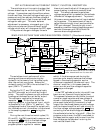
The beam current feedback circuit uses a PNP video
transistor
954 to direct most of the beam current to the
auto bias circuit while passing the voltage waveform,
from the video amplifiers to the CRT cathodes. Diode
958 and capacitor 956 insure that no video waveform
distortion occurs. An additional benefit of this circuit is
that it protects the video amplifiers from the destructive
arc energy. Resistors 948 and 955 divide energy due
to CRT arcing, between the video amplifier transistors
and the beam current feedback transistor
954 . The
beam current is filtered by capacitor 941 and resistor
C10 and is buffered by an operational amplifier, which
translates the beam current into a low impedance
voltage. This voltage is applied to a coupling capacitor
921 through a 200 ohm resistor C8 .
The 200 ohm and the 68.1K resistor
C3 forms the
program value which sets the black level voltage via the
action of the program pulse.
Capacitor 922 is used to stabilize the
transconductance amplifier which is used at the channel
input of the auto bias IC
927 . The auto bias IC stores
the bias voltage of this channel in capacitor
895 at pin
21. This voltage is buffered by an internal amplifier,
with output at pin 20, which is connected to the Blue
video amplifier bias control input.
Resistor 908 , 910 , and 911 are part of the auto
bright circuit. They are used to sum the bias voltage of
each of the three channels via a voltage node at the auto
bright amplifier, 920 pin 9. The resulting output
voltage then controls the screen grid via transistor 850 .
Resistor
881 protects the CRT grid from excessive
current during arcing. Capacitor
878 supplies a low
AC impedance to GND to insure that the CRT gain is
constant during each horizontal line. Resistor 858 and
914 defines the current gain of, and stabilizes, the auto
bright control loop.
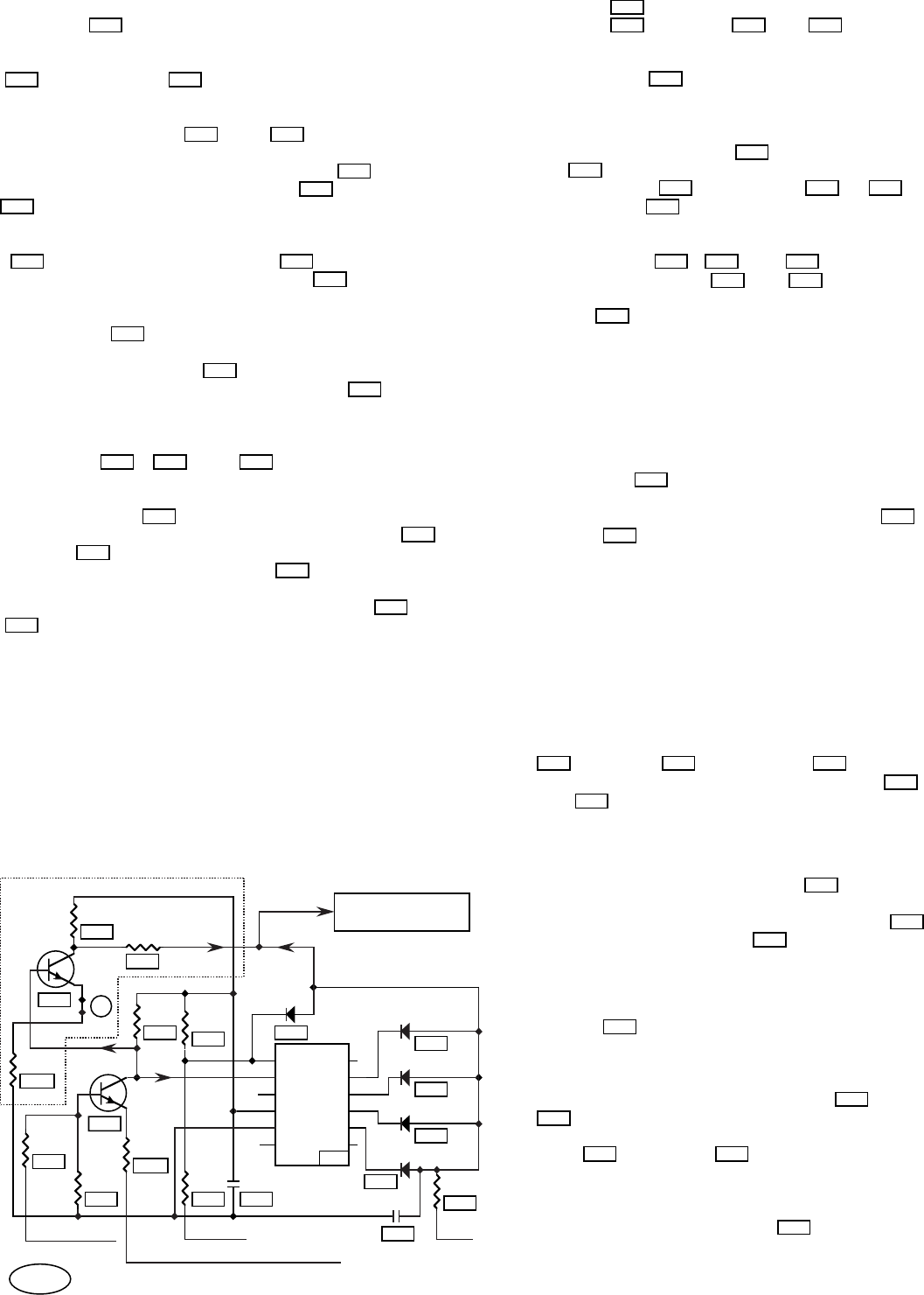
CRT AUTO BIAS AND AUTO BRIGHT CIRCUIT DESCRIPTION.
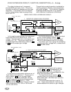
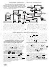
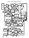
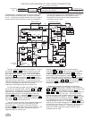
CRT AUTO BIAS, VERTICAL SYNC CIRCUIT DESCRIPTION.
The auto bias vertical sync comes from from a buffer circuit
for 15KHz operation. For 31KHz operation this signal is
generated by a delay counter. For both cases, the vertical
boost pulse is "and" connected with the Vertical Osc. O/S to
provide flicker free operation and laser beam protection. In
the case of vertical deflection failure, the loss of the boost signal
causes the auto bias vertical sync to stop, which stops the auto
bias function, and blanks the screen via the vertical blanking
circuit, thus providing for laser beam protection.
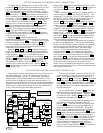
The vertical oscillator one shot (LA7851 pin 16)
supplies the start timing for the auto bias vertical
sync. This signal is conducted to the emitter of
379 by jumper 389 . The base of 379 is connected
to the retrace boost pulse by resistor divider
383
and 384 . Combining these signals in this way
produces a collector waveform which has the vertical
oscillator one shot timing and is dependent on the
retrace boost pulse.
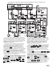
For the 15KHz case, transistor
100 inverts the
vertical oscillator one shot signal to produce the
CRT auto bias vertical sync signal. Resistor
099
is the pullup and resistor 006 reduces the
chance of arc damage to the transistor.
For the 31KHz case, the vertical oscillator one
shot signal is directed to the clear of the 7 bit
counter
100 . This O/S time out must occur after
the autobias delay time out and come before the
bias active pulse from the CA3224E. When the
clear is low, the counter counts horizontal pulses,
by the clock connected voltage divider 099 and
201 . When the counter outputs ones at each diode
connected output, further counts are inhibited by
diode 006 and pullup 381 . This diode "or" signal
is also used for the CRT auto bias vertical sync.
The delay is set to locate the grid pulse generated
3 faint lines at the top of the screen with full
vertical deflection. Capacitor
091 produces a
delay to avoid a race condition between the counter
clock and the auto bias horizontal sync.
910
C3
921 C8
C10
954
954
958 956
948
908
914
858
878
881
850
920
895
927
909
911
920
856852
871
874
933
928
C7C4
906905903
928
855 873
884
888
891
920
922
955
941
099
384
201
091
089 379
383
100
379
100
006
099
006
381
72