


RC4
483
482
486
500Ω
750Ω
1K
Vertical
Raster
Position
Vertical
Size
RC8
RC6
RC3
Remote Control Board
.1-.3VCD
3.8Vpp 17,E5
Vs
4-6VDC
2.8Vpp 18,D5
Vs
5.5-6.5V
1.4Vpp
23,F4
Vs
GND
18 17
GND
410
VERT.
OSC.
± SYNC INPUT
VERTICAL VERTICAL
OSCILLATOR
OSC. O/S
HEAT
SINK
378
362
365K
414
.01uF
361
127K
12 34 567 8 910
+12V
Ramp
Gen.
Slope
out
Vert.
Drive
Retrace
Booster
Drive
LA7838
Vertical
Deflection
004
510Ω
375
401
1uF
380
470uF
388
392
391
393
68.1K
390
385
1.2Ω, 1W
403
V. osc.
363
203
0Ω
V
377
CPC1058
.1uF
2.2M
ADJ.
V.+12V
376
100uF
+
5-6VDC
1.4Vpp 22,E5
Vs
V. size
Control
50/60Hz
5.5-6.4V
3Vpp 21,D5
Vs
One Shot
Tr.
R/C
out
374
.01uF
402
44.2K
Reset
Ramp
Reset
Ramp
369
1,000pF
+
+27V
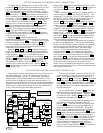
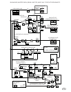
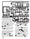
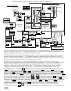
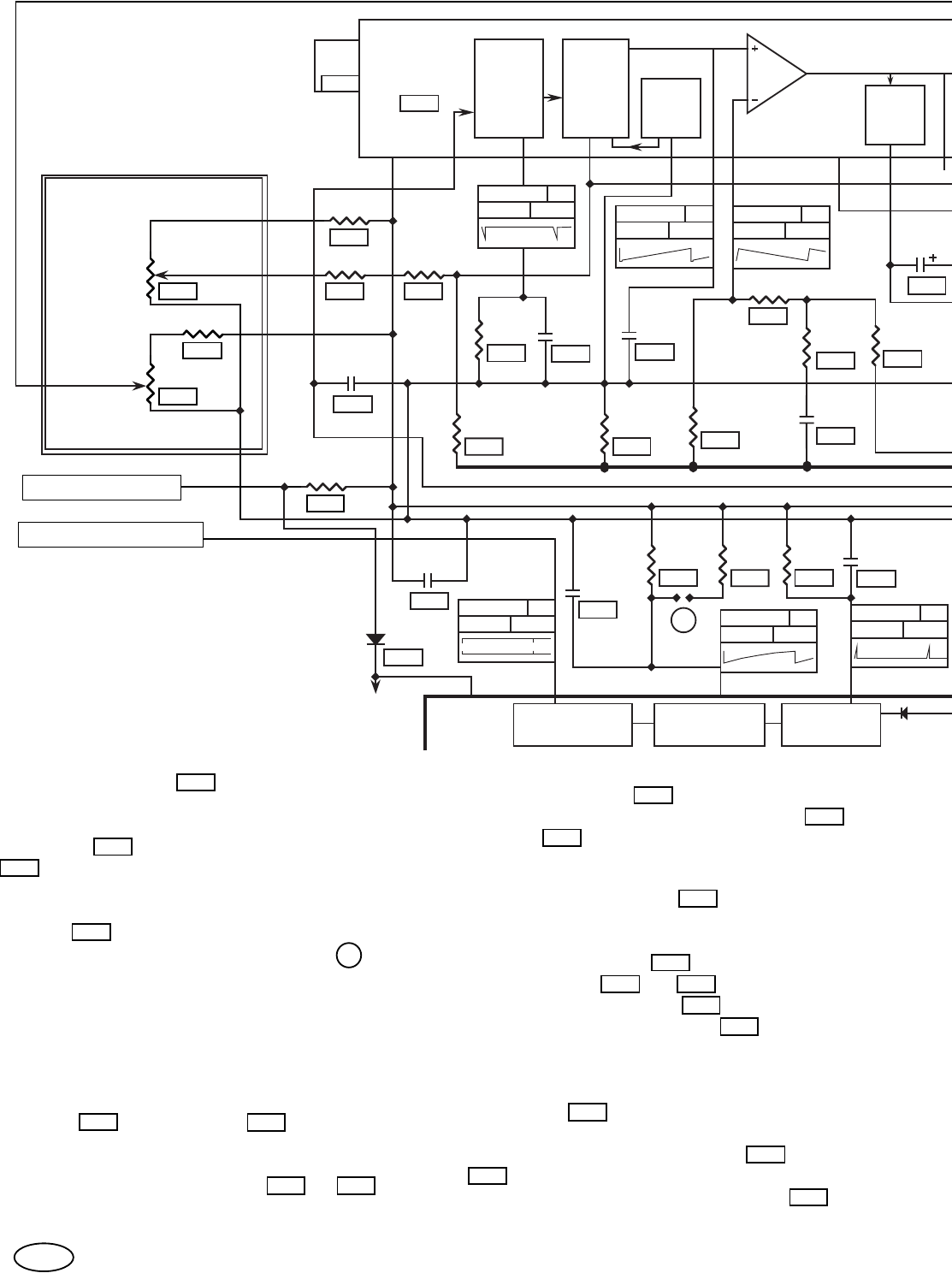
VERTICAL DEFLECTION CIRCUIT DESCRIPTION.
Vs
VERTICAL SYNC
+12V SUPPLY
5.5-6.5V
1.2Vpp 19,D5
Vs
or
20 19
V+
VERTICAL
367
18Ω
1N4005
382
H.+12V
VERTICAL
See
Table
The vertical sync comes from the
synchronized vertical sync interface
circuit for monitors without interlace.
For monitors with interlace the vertical
sync comes from the sync comparator
via a coupling capacitor and bypasses
the synchronizing circuit. Pin 19 of the
LA7851 is the vertical sync input and will
start the next oscillator cycle on either the
positive or negative sync pulse. The vertical
oscillator capacitor
410 discharges to 4 volts
on the leading edge of the vertical sync by the
action of an internal transistor and resistor.
Capacitor 410 is then charged by resistor
362 until the next sync pulse or to
8 volts, which ever comes first. The V. osc.
frequency is set low such that the adjustment
resistor 363 can be used to act as a vertical
hold adjustment. Solder connection V is
used to make this adjustment.
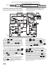
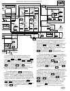
The one shot in the LA7838 clamps the ramp
forming capacitor 401 to 5 volts for about half of
the vertical retrace time. Capacitor 374 and
resistor
402 form the RC circuit for the ramp
reset one shot.
The ramp capacitor 401 is charged by current
from a current generator with a 6 volt input node
at pin 4. The vertical size is adjusted by the
vertical size control
482 which is connected to pin
4 via resistors 003 & 375 . The adjustment
range is set by resistor 375 and the maximum
deflection is set by resistor 403 . A third input
to pin 4 comes from the vertical linearity circuit.
This circuit uses the above and below GND parts of
the vertical current waveform separately.
Transistor
411 conducts when the vertical current
waveform is below GND. This transistor’s emitter
is referenced to GND by diode
406 and resistor
371 . The emitter is connected to the vertical
current waveform through resistor
407 which is
adjusted for each tube and yoke combination.
80
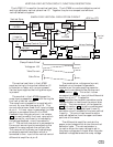
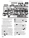
The vertical oscillator triggers the vertical
oscillator one shot, which outputs a pulse to
trigger the vertical sync input, pin 2, of the
LA7838. This one shot is also used to
synchronize the CRT auto bias IC.
Resistor 361 & capacitor 414 set the
timeout which must be longer than the CRT
auto bias Vs delay and shorter than the
vertical blanking. Resistors 370 & 408
supply the pullup for this one shot.
362
370 408
414
361
363
403
384
003
402
407
371
411
375
406
410
482
410
401
375
401
V