


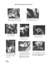

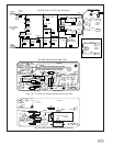
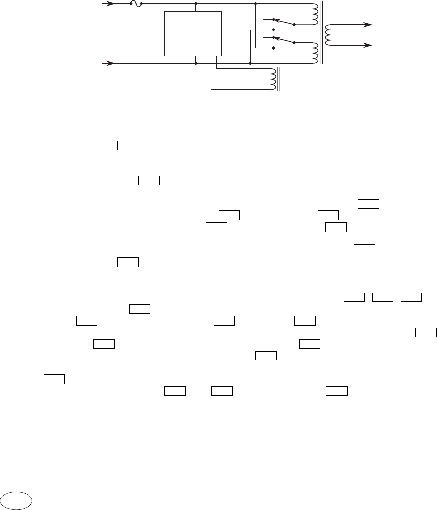
Circuit Description.
The fuse 506 protects the mains wires and the control PCB.
The power transformer has two internal 2 amp temperature sensitive fuses.
Each primary half has one, built in, series connected fuse.
A resettable fuse 507 is connected to the relay driver power supply.
This fuse protects the relay control circuit from square wave input which would
occur if an inverter is used as the power source. Capacitor 512 supplies
current from the line to capacitor 513 through diode 510 which forms the, relay
control, power supply. Diode 511 charges capacitor 512 during the negative
going part of the line wave. Transient Voltage Suppressor 516 regulates the
24V power supply and protects the relay coil from over heating.
The Mos Fet 514 shorts out the 24 volt power supply when the input line
voltage is 240VAC.
The input line voltage, at which the Mos Fet turns on, is set by the Mos Fet turn
on voltage (about 4V), the voltage drops across resistors 509 , 505 , 504 , and
the zener diode 503 . 154VAC is the approximate line voltage at which the
relay 518 switches. Capacitor 508 and diode 502 keep the Mos Fet turned
on for the complete AC cycle to eliminate ripple current in the capacitor 513 .
Resistor 504 limits the peak current to capacitor 508 to avoid relay switching
due to line transients. The zener diode 515 which is connected from the Mos
Fet source to gate protects the Mos Fet gate against over voltage. Resistor
519 is needed to limit the mains current when the relay arcs across both sets of
contacts. Capacitors 517 and 520 reduce the relay T518 contact noise which
may be generated when switching.
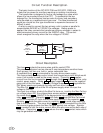
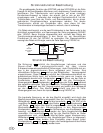
The basic function of the ISO XFR-75W and ISO XFR-100W is to
isolate the line power for monitors requiring an isolation transformer.
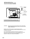
The transformer is designed to have a low leakage flux value which
allows it to be mounted close to the CRT. To accomplish the low
leakage flux, the transformer has two sets of primary and secondary
coils mounted on a modified toroid type core. The ideal transformer
would be a toroid but this type transformer is expensive because it is
difficult to wind.
A relay is used to connect the two primary coils in series or parallel to
accommodate 240VAC or 120VAC line voltages. Before power is
applied, the relay connects the transformer primary windings in series to
avoid excessive primary current for the 240VAC case. The control
circuit energizes the relay when the line voltage is 120VAC.
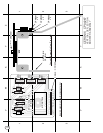
240VAC
or
120VAC
Relay Control
Output
240VAC
or
120VAC
50 or 60 Hz
Input
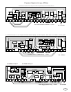
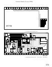
Circuit Function Description.
T506
T505T509
T503
T512
T514
T516
T511
T510T513
T512
T507
T520T517
T515
T518
T504
T508 T502
T513
T504
T508
T519
T518
116