


From MAIN PCB
+12V
+127fV
+120V Source
+16V
FIL.
870
872
Grid Pulse
Vs-23 to -27Vdc
10Vp-p 95uS
874
1.87K
1N4937
847
857
+
876
100K
FDH400
FIL.
+12V
+16V
+127V
TC 8
TC 1
TC 4
GND
TC 2
TC 11
TC 12
Fil. GND
868
GND
1N4005
848
1uF
846
50V
FIL.
+120V
150
875
1/2W cc
Ω
.1uF
816
.1uF
801
30Ω
859
860
962
0Ω
-16V to-25V
12
DAG GND
5
EHT
8
6
11
97
1
Socket Board
PCB
Degaussing Coil
970
800
971
G1 G2 Focus
10
SOCKET
877
2.2K
EHT
FOCUS
SCREEN
1/2W
1K
1/2W
855
881
150Ω
1/2W
880
961
Green
Wire
10K 1/2W
873
150Ω
1/2W
882
330pF
871
0VDC
56V 31uS
Hs
0Ω
896
FDH
400
835
900
851
RED
GREEN
BLUE
883
FDH
400
845
FDH
400
886
FDH
400
899
FDH
400
849
FDH
400
959
2.2nF
100K
856878
1/2W
853854
GND
Auto Bright Control Output.
CC1
CC2
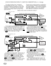
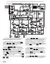
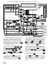
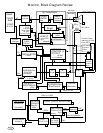
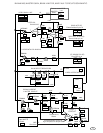
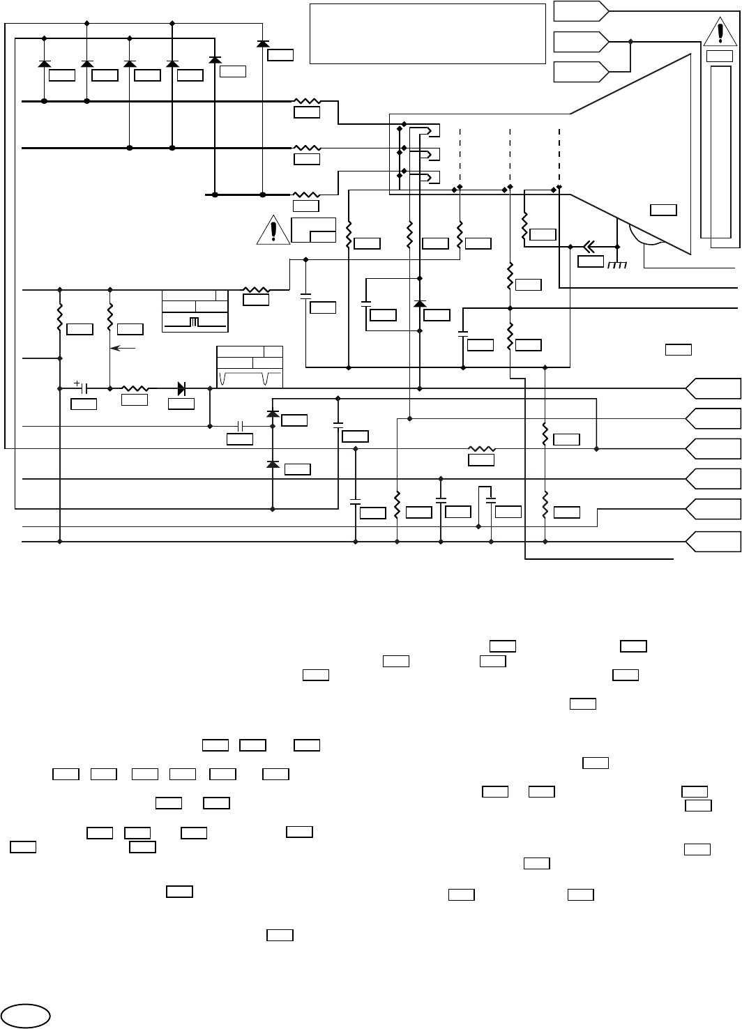
VIDEO BOARD POWER SUPPLY AND ARC PROTECT SCHEMATIC.
From Video Amp.
+120V
+127fV
70
+
DAG GND
1/2W
1/2W
1/2W
50V
18Ω
879
200V
100uF
CC3
Caution! 2 pin degaussing coil plug (CC1 &
CC2) must be plugged in such that the pin
with the extra wire is closest to the fuse.
UNPLUG WHEN REPAIRING MONITOR.
The high voltage in the CRT, through an arc, can
be conducted to any tube socket connection on the
video board. To reduce the danger of these arcs
causing component failure, a number of arc current
paths are provided. The tube socket has integral
spark gaps which conduct arc current to the tube
ground (aquadag). through dissipation resistor 882 .
The clamping voltage of the spark gaps to the
cathodes and G1 is about 1.5KV.
The peak arc current to the video amplifier
outputs is limited by resistors 900 , 851 , & 883 .
Each amplifier output is connected to two clamp
diodes
835 , 899 , 845 , 849 , 886 , & 859 to
provide a current return to ground via the power
supply filter capacitors
175 & 860 . The grid pulse
drive to G1 is protected by a low pass filter made up
of elements
855 , 871 , & 873 . Resistors 881 ,
856 and capacitor 878 also form a low pass filter for
the G2 to auto bright control output connection.
A dissipation resistor
880 is connected to the
focus spark gap to match the impedance of the
aquadag connection. This reduces reflections and
helps dissipate the arc energy. Resistor
879
supplies an additional ground path for arc energy.
G1 is connected to a negative voltage to increase the
cutoff voltage which reduces the dot size and produces a
sharper picture. This negative voltage is generated by
rectifying the negative peaks of the filament flyback
pulse with diode
870 , filter capacitor 868 , and resistor
872 . Resistor 872 is used to adjust the negative G1
voltage for different FBTs. Resistor 876 provides a
fixed load to stabilize the -G1 voltage. The grid pulse is
developed across load resistor
874 by a PNP transistor.
The 120 volt line, which is also generated by the
filament voltage, is used to supply the video amplifier
output bias current. Capacitor 857 translates the GND
referenced filament flyback pulse to the 127 volt line.
Rectifier diodes
847 & 848 and filter capacitor 846
generate the V+ minus 7 volt supply. Capacitor 857 is
also used to adjust this voltage for different FBTs.
The filament voltage is adjusted by capacitor 854
and diode (or resistor) 853 .
Resistor 859 and capacitor 860 decouples the video
amplifiers from the 127 volt line. This filter is needed,
in some models, to eliminate video amplifier distortion
caused by ripple current on the V+ line. This ripple
current is caused by the, V+ minus 7 volt line, power
supply.
870
856
855 871
878
873
881
835 899 845 849 886 859
883851900
876
874
857
848847 846
857
854
860
853
859
880
868
872872
882
175 860
879
Power supply voltages shown, are
for the 2793-CGA monitor.