


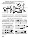
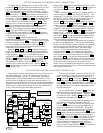
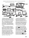
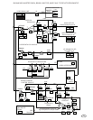
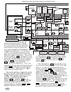
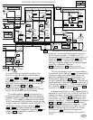
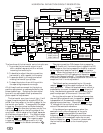
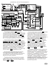

BLANKING, MASTER GAIN, AND FAULT CIRCUIT DESCRIPTION.
76
Horizontal blanking ( ) is added
to the gain line by transistors 072 . This
transistor pulls down on the gain line when
the flyback pulse is high. Capacitor 081 is
charged by diode 080 and resistor 093 such
that, as soon as the flyback pulse starts going
positive the NPN transistor 072 turns on
and horizontal blanking starts. The time
constant of capacitor 081 and resistors 078
and 093 is chosen such that the capacitor
will lead the FBP on the downward slope and
turn the horizontal blanking transistor off
just at the end of the FBP. This advanced
timing compensates for the turn off delay of
transistor 072 .
Vertical blank time is started when a low
going pulse from the LA7851 pin 16 causes
the output, pin 1, of the dual comparator
210 to go low. Capacitor 207 is discharged
through resistor 208 at this time. After the
end of the LA7851 pulse, the capacitor
207 holds the output, pin 7 of the
comparator, low until the bias active pulse
recharges the capacitor 207 through diode
253 . During the high time of the bias
active pulse, the comparator output pin 7 is
still low, because of the voltage drop across
the diode 253 . The end of vertical blank
time occurs when the bias active line
returns to it's high impedance state. The
capacitor 207 holds the charge from the
bias active pulse until the next vertical
blank time. The advantage of this type of
vertical blanking circuit is that, if the CRT
auto bias IC fails to produce a bias active
pulse, the screen stays blanked. This action
protects the CRT when the vertical
deflection system fails since the output of the
LA7838 boost pulse is needed for the CRT
auto bias vertical sync (CA3224E pin 8).
The video gain line will source up to 32mA
during blank time, which is the reason for
buffering the vertical blank comparator with
a PNP transistor 212 .
Resistors 251 and 252 supply a voltage
that is midrange relative to the LA7851 pulse
for maximum noise immunity.
Resistors 248 and 250 also supply another
midrange voltage for the bias active pulse
and the, vertical blanking, hold capacitor
207 to work against. Resistors 211 and
368 are used as jumpers.
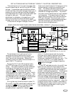
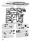
The beam current limiter circuit uses the
base to emitter voltage of a darlington
transistor 036 to set the maximum beam
current. To sense the beam current,
capacitor 010 integrates the current pulses
produced by rectifying the high voltage
flyback pulses. The beam current is
converted to a voltage across resistor 009 .
This voltage is applied to a long time
constant RC circuit, resistor 011 and
capacitor 014 , before it is sensed by the
darlington transistor. The sharpness of the
limiting response is set by resistors 012 ,
065
and 066 . Transistor 071 then,
reduces the video gain by pulling down on
the master gain line upon excessive beam
current. The beam current is also reduced if
the FBT temperature sensor exceeds 74°C.
Resistor 020 sets the temperature at which
this circuit becomes active. The resistance
of thermistor 180 decreases with increasing
temperature until the voltage at the cathode
of diode 018 is low enough to turn on
transistor 036 which turns on transistor
071 and darkens the screen.
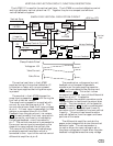
The master gain control 485 is connected
to the video gain line through a 1K resistor
062 . The voltage range of the video gain
line is programmable via resistors 064 , 076
and solder bridges at S , T , & U .
The solder bridges may connect resistors
244 , 245 , 258 , and 260 to the video gain
line. This arrangement permits a variety of
input signals and picture tubes to be used
with the same monitor PCB.
The fault circuit senses the temperature
or beam current line with a, comparator
connected, OP Amp. 033 at pin 2 (– input).
The + input of the OP Amp. is biased to
3 volts by a voltage divider, resistors 034
and 037 . The output of the, OP Amp. is
connected to a low pass filter, resistor 017
and capacitor 035 to insure that the fault
circuit does not become active on power up.
Transistor
008 conducts the fault signal to
the over voltage protect input of the power
supply IC. Resistor
005 protects the voltage
translator transistor 008 and the power
supply controller IC.
485
S
UT
H
B
062
064
076
244 245
258
260
072
080
081
072
078
093
210
207
081
093
072
208
212
251 252
248
253
207
207
207
253
250
211
368
036
010
009
011
014
012
071
066
065
005
020
180
018
033
071
207
036
008
035
034
037
008
017