


grace design m201
owner’s manual
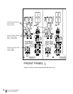
12
The front panel interface features a calibration mode that allows precise adjustment of
the A/D sensitivity. To recalibrate one or both of the input sensitivity configurations,
simply do the following:
1) Disconnect AC power from the m201.
2) Remove the 8 top cover screws using a #2 Phillips screwdriver. Lift the top cover
off the unit and set it aside.
3) Reconnect AC power to the m201 and turn it on.
4) Connect a signal generator to the A/D LINE inputs. Set the signal generator output
to +4dBu @ 1kHz (1.29V rms).
5) Turn on the m201 A/D converter and select LINE as the A/D input source.
6) To enter CAL mode, press and hold the INPUT SENS button for approximately 3
seconds. The normal operation displays will extinguish and the CAL indicator will
begin flashing indicating CAL mode is active. The current input sensitivity range
(A) or (B) will be illuminated along with that range’s current sensitivity calibration
(shown as “dB Headroom” in the bottom left of the meter display).
7) Press and release the INPUT SENS button to select the range (A) or (B) that you
wish to calibrate.
8) Press and release the A/D SOURCE button to scroll through the 4 available sensi-
tivities until the desired setting is illuminated.
In calibration mode, the digital audio meter is configured such that the “0” position is
the target sensitivity level. The meter then indicates the current signal level versus this
target sensitivity. The meter will display a window centered around the target sensitiv-
ity with a +/- 0.4dB width (in 0.1dB increments). When the sensitivity adjustment on
the A/D converter is calibrated for the selected setting, only the “0” LED will be illumi-
nated. If the signal level is high, the 0 indicator will be illuminated along with the error
(in 0.1dB increments) to the right of 0. If the signal level is low, the 0 indicator will be
illuminated along with the error (in -0.1dB increments) to the left of 0.
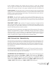
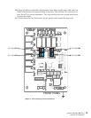
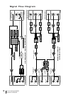
On the m201 A/D module, trim pots are used to adjust the (A) and (B) ranges for each
channel. Each of these are labeled on the A/D module circuit board <figure 3>.
9) Locate the appropriate trimmer for the channel you wish to adjust. If the current
signal level is high, you need to decrease the A/D sensitivity. Using a non conduc-
tive tool, turn the appropriate trim pot counter-clockwise to reduce the level until
only the “0” is illuminated on the m201 meter. If the current signal level is low, you
need to increase the A/D sensitivity by turning the appropriate trim pot clockwise
to increase the level until only the “0” is illuminated on the LED level meter.