


M+S WIDTH
100m
70m
30s
30m
70s
50m
50s
GRACE DESIGN USA
m201microphone preamplifier
HI-Z
1
48V
HI-Z
130V
ribbon
(
+10dB
)
20
30
40
50
60
INPUT MODE
+48V - 20dB
HI-Z
2
48V
HI-Z
130V
ribbon
(
+10dB
)
20
30
40
50
60
INPUT MODE
+48V - 20dB
A
B
G
F
E
D
C
H
I
grace design m201
owner’s manual
4
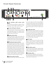
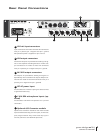
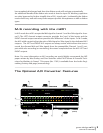
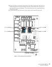
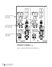
Front Panel Controls
A
24 position gold contact gain
switch
Each gain control has 24 positions and adjusts the volt-
age gain from 18dB to 64dB in 2dB steps. In ribbon
mode the gain range is 28dB to 74dB in 2dB steps.
B
bi-color LED peak indicator
The LED peak indicator, which monitors the output sig-
nal level, turns green at -14dB and switches to red at
+16dB (12dB before clipping). The threshold level for
peak indication is adjustable on each channel (see the
calibration section of this manual).
C
input mode switch
The input mode switch is used to select between the
various types of inputs available with the m201, includ-
ing standard 48V, ribbon mic mode, HI-Z, or the optional
130V DPA™ inputs. Refer to the m201 block diagram at
the end of this manual for signal routing details.
D
48V phantom power switch
The phantom power switch (labeled +48V) connects
the +48V power supply to pins 2 and 3 on the XLR in-
put connector. This switch illuminates red. It should be
noted that the LED in this switch actually monitors the
phantom power voltage at the input. With no micro-
phone connected, the LED will continue to illuminate
for approximately 10 seconds after the phantom power
is turned off as the filter capacitors discharge. As well,
even if the phantom power is switched off, the LED will
illuminate if voltage is being fed from an external source.
(i.e. when using a direct split in a remote recording ap-
plication.) Also, the +48V switch is used to activate the
+130V DPA™ mic power if this option is installed.
E
polarity reversal switch
The polarity reverse switch reverses the absolute phase
of the music signal at the input of the preamplifier.
The switch illuminates green and provides power for
a sealed gold contact relay located on the preamplifier
circuit board. This eliminates signal wiring to the front
panel and switch contact performance problems. The
polarity reverse function is active for all input connec-
tors.
F
-20dB pad switch
The 20dB attenuator switch attenuates the input signal
20dB. The switch illuminates amber when engaged.
Like the phase reverse switch, this switch controls a
sealed gold contact relay on the preamplifier circuit
board. With the -20 switch engaged, the effective gain
range becomes -2dB to 44dB. The 20dB attenuator is
active for 48V Phantom, ribbon and (optional) DPA in-
puts. It does not affect the HI-Z inputs.
G
HI-Z input
This 1/4 inch TRS input is active when the input mode
switch is in the HI-Z position. Suitable for any high
impedance source such as: bass guitar, acoustic guitar,
electric guitar, keyboards, etc... This input is can be used
balanced with a TRS connector or unbalanced with a TS
connector.
H
M-S width control
This knob controls the ratio between the Mid and Side
signals in an M-S recording setup. Please see the ‘pre-
amplifier operation’ section of this manual for complete
information regarding this feature.
I
standby switch
Connects the mains voltage and turns on the m201
When depressed the pushbutton will illuminate green
and the preamplifier will be on. When released the pre-
amplifier will be in standby mode.