


grace design m201
owner’s manual
14
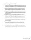
Maintenance
The model m201 was designed to be maintenance free for many years. It is highly
unlikely that your unit will require service. However, there are two adjustments that
may need to be made from time to time. These procedures should be made only by a
qualified service technician or at the Grace Design factory.
PEAK LED ADJUSTMENT PROCEDURE
The peak LED threshold levels may be adjusted to a user defined operating level. This
circuit is set at the factory with the green threshold at -14dBu and the red threshold
at +16dBu. The relationship between the two thresholds is fixed. The procedure for
adjusting the greed / red threshold follows:
EQUIPMENT NEEDED
• Sine wave audio signal generator or oscillator output from a mixing console.
• Audio level meter or an RMS Volt meter with dBu or dBm scales
• Plastic alignment tool or small screwdriver
• Appropriate interconnect cables
• #2 phillips head screwdriver
PROCEDURE
1) With the power off, remove the eight phillips head screws from the top cover and
remove it from the m201
2) Set all of the gain controls to the 30dB position
3) Connect the audio generator to the input of channel 1
4) Set the generator output level to approximately -20dBu @1KHz.
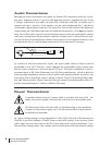
5) If the generator has an unbalanced output, refer to figure 2 below for termination
information
6) Connect the level meter to the output of channel 1.
7) If the level meter has an unbalanced input, refer to <figure 1> for unbalanced
output termination information.
8) Apply power to the generator, preamplifier, then the level meter.
9) Adjust the generator output level so that the preamplifier output level is at the
desired red threshold. If the proper level can’t be reached, adjust the preamplifier
gain control.
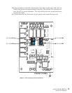
10) Locate VR2A (VR2B for channel 2) (see <figure 3>) on the channel 1 audio circuit
board and adjust until the peak LED is between green and red. The color should
appear amber when the setting is correct. Repeat this procedure for channel 2.
11) If it is desired to calibrate the peak indicator to a specific converter/recorder
input level, simply connect the output of the preamplifer to the converter/re-
corder. Adjust the signal generator so that the desired peak level is indicated on
the recorder and then adjust VR1 until the peak LED is between green and red.
INPUT OFFSET ADJUSTMENT