


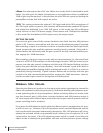
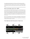
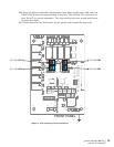
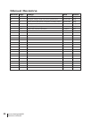

<figure 3 - A/D sensitivity trim pot locations>
8
4
C
-15VA
U9
C40
P4
C42
7
4
C
5
4
C
7
3
R
2
4
R
C46
+6.5V
TP
5 TP6
+3.3V
1
4
R
4
5
C
3
4
R
4
4
R
P5
R31
4
3
R
2
V
E
R
6
3
1
T
A
5
3
R
R38
K2
K3
Q1
C10
K1
P1
FD1
C13
J2
U4
C20
R9
TP1
+15VA
+18V
TP2
1
n
i
P
J5
C2
9
P3
U11
0
3
C
J4
-18
V
TP3 TP4
D1
D2
R1
0
R16
U5
Q2
R13
4
1
R
D3
D4
1
5
1
R
C21
R19
C31
8
D
8
2
R
R29
K7
4
Q
C36
K4
K5
K6
C6
P2
C4
D5
D6
Q3
C11
C15
C14
R12
R11
2
1
C
U3
D7
C1
7
R22
R2
6
R2
3
6
2
C
C25
C3
2
4
2
C
C27
C41
R32
3
4
C
0
5
C
0
1
U
6
1
U
5
1
U
R39
1
5
C
P6
A VR3
B
VR4
VR2 A
VR1 B
3362
1
3
3362
1
3
3362
1
3
3362
1
3
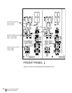
FRONT PANEL
CH2 (B): VR4
CH2 (A): VR3
CH1 (B): VR1
CH1 (A): VR2
grace design m201
owner’s manual
13
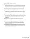
10) Once all desired calibration adjustments have been made, press and hold the
INPUT SENS button for approximately 3 seconds. This will exit CAL mode and re
-
turn the A/D to normal operation. The new settings are now stored until future
changes are made.
11) Power down the unit, disconnect the AC power and reinstall the top cover.