


< >
14 16 18 20 0 0.1 0.2 0.3 0.4-0.3 -0.2 -0.1-0.4
LEVELHEADROOM
(
dB
)
1
2
-60 -50 -40 -32 -28 -24 -20 -18 -16 -14 -12 -10 -8 -6 -5 -4 -3 -2 -1 0
CAL
INT WORD LOOP
sLOCK
OFF
PRO
2WIRE44
48 88 96
176
192
MSCH1-2
LINE
CONS
OVER
OVER
BA
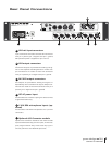
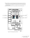
FS SELECT CLOCK SOURCE ADC MODE
INPUT SENS
PEAK RESET
ADC SOURCE
/ MODE
(hold)
H
E
J
F
A
B
I
G
C
D
grace design
m201
owner’s manual
9
has completely discharged and then the ribbon mode will activate automatically.
An additional benefit of the ribbon mic mode is that the input DC blocking capacitors
are relay bypassed to further simplify the m201’s signal path. Incidentally, the ribbon
mode works very well with many lower output dynamic microphones as well as ribbon
types.
M-S recording with the m201
In M-S mode the m201 accepts the Mid signal in channel 1 and the Side signal in chan
-
nel 2. The LEFT channel output connector provides the “sum” of the inputs and the
RIGHT channel output connector provides the “difference” of the inputs. In M-S mode,
the M-S width control adjust the ratio of Mid signal to Side signal in the dedicated M-S
outputs. The LEFT and RIGHT M-S outputs are always active which allows the user to
record the discreet Mid and Side signals from the preamplifier Channel 1 and 2 out
-
puts while also recording (or monitoring) the stereo composite from the M-S LEFT and
RIGHT outputs.
Note: For more information on M-S recording we would highly recommend the AES
paper written by Wes Dooley and Don Streicher called “M-S Stereo: A Powerful Tech
-
nique for Working in Stereo”. This paper (No. 1792) is available from the Audio Engi
-
neering Society web page (www.aes.org).
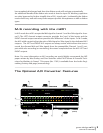
The Optional A/D Converter Features