


each of the three channels (that is, exactly what will be output, in terms of light, for the given values of
red, green, and blue). This may be expressed by the following diagram:
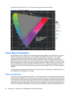
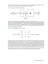
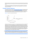
Figure A-2 Model of Standard Display Device
Here, the input RGB values are first modified by the appropriate transfer function (γ
R
, γ
G
, or γ
B
); this
operation may be viewed as being performed by three look-up tables (LUTs) of the appropriate width
and depth. The modified RGB values (R′, G′, and B′) are then mapped to the resulting output light levels
of the correct intensity and color. This may be viewed as a matrix multiplication operation (A) involving
the R′G′B′ values and the appropriate XYZ tristimulus values for the specific display device primaries,
luminance, and white point in question:
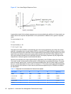
Figure A-3 Matrix Multiplication of Input Values
In essence, the R′, G′, and B′ values may be seen as “gain controls” on three light sources whose peak
outputs are described as (X
R
,Y
R
,Z
R
), (X
G
,Y
G
,Z
G
), and (X
B
,Y
B
,Z
B
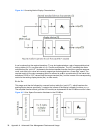
). The display device itself – in this case,
the LCD module used in the LP2480zx monitor – of course has its own native characteristics which may
be modeled as described above. The problem of emulating a different (presumably, standard) output
device characteristic is then one of adding a “transform” block (T, in the diagram below) which will modify
this native characteristic such that the overall system emulates the desired performance. In terms of the
above diagram, if the combination of γ
S
and A
S
represent the desired standard characteristic, it is the
function of the transform block T to correct the native display characteristics (γ
D
and A
D
) such that the
output (TD) of this system matches that of the standard device, for the same input values:
Color Space Emulation 35