


KRAMER: SIMPLE CREATIVE TECHNOLOGY
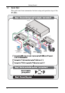
Connecting the TP-305A UXGA-Audio-RS-232 Line Receiver/DA
10
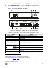
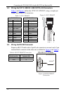
5.3 Wiring the CAT 5 LINE IN / LINE OUT RJ-45 Connectors
Table 3
and Figure 5 define the UTP CAT 5 PINOUT, using a straight pin
to pin cable with RJ-45 connectors:
Table 3: CAT 5 PINOUT
Figure 5: CAT 5 PINOUT
EIA /TIA 568A EIA /TIA 568B
PIN Wire Color PIN Wire Color
1 Green / White 1 Orange / White
2 Green 2 Orange
3 Orange / White 3 Green / White
4 Blue 4 Blue
5 Blue / White 5 Blue / White
6 Orange 6 Green
7 Brown / White 7 Brown / White
8 Brown 8 Brown
Pair 1 4 and 5 Pair 1 4 and 5
Pair 2 3 and 6 Pair 2 1 and 2
Pair 3 1 and 2 Pair 3 3 and 6
Pair 4 7 and 8 Pair 4 7 and 8
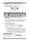
5.4 Wiring the RS-232 Connector
Prepare an RS-232 cable with a 9-pin D-sub connector at one end, and a 2-pin
terminal block connector at the other end, as defined in Figure 6
and Table 4:
Table 4: RS-232 PINOUT Connection
Figure 6: RS-232 PINOUT
Connection
Attach the 9-pin
D-sub Connector
To the Terminal Block
Connector PIN:
PIN 3 TX (1 and 2)
PIN 5 G
TX
PIN 5 Connected to GND
PIN 3 Connected to RxD
1
2
3
4
5
6
7
8
9
To PC (9-pin D-sub)
RS-232 to TP-305A
G