


KRAMER: SIMPLE CREATIVE TECHNOLOGY
Getting Started
2
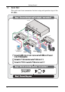
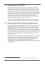
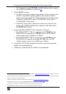
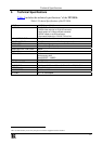
2.1 Quick Start
This quick start chart summarizes the basic setup and operation steps of the
TP-305A.
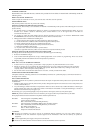
Step 3: Connect the power
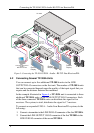
Step 1: Connect the input and the outputs - see section 5
Connect the UXGA video and audio outputs, and the RS-232 port (if required)
to the TP-123 transmitter
Connect the TP-123 transmitter to the TP-305A via CAT 5
Connect the TP-305A to up to five TP-124 receivers via CAT 5
Connect the UXGA video and audio outputs, and the RS-232 port (if required)
to the TP-123 transmitter
Connect the TP-123 transmitter to the TP-305A via CAT 5
Connect the TP-305A to up to five TP-124 receivers via CAT 5
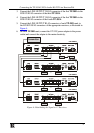
Set the Hs and Vs
polarity switches
Set the Hs and Vs
polarity switches
Step 2: Set the underside switches - see section 5Step 2: Set the underside switches - see section 5
AOUT
UDIO
LIN
INE
TP-124
XGA OUT
XGA/Audio/DataLineReceiver
TP-124
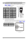
RS-232
GND
TXD
A
NALOG
S/PDIF
12V DC
LOUT
INE
RS-232RS-232
XGA IN
TP-123
XGA/Audio/DataLineTransmitter
GND
TP-123
RXD
AIN
UDIO
12V DC
AOUT
UDIO
LIN
INE
TP-124
XGA OUT
XGA/Audio/DataLineReceiver
TP-124
RS-232
GND
TXD
A
NALOG
S/PDIF
12V DC
S/PDIF
12V DC
LO
INE UTPUTS
12345
A
NALOG
UXGA OUT
RS-232
TP-305A
GTx
AOUT
UDIO
LIN
INE
Computer Graphics /
Audio /
RS-232 Control
STP Cable
Range up to
300ft (100m)
STP Cable
Range up to
300ft (100m)
STP Cable
Range up to
300ft (100m)
Plasma
Display
AV-Receiver
Plasma
Display
Plasma
Display
VGA
RS-232
Audio
VGA
Audio
RS-232
VGA
RS-232
Audio
VGA
RS-232
Audio
Audio
2
2
1
1
1
3
3