


Your TP-305A UXGA - Audio - RS-232 Line Receiver/DA
5
4 Your TP-305A UXGA - Audio - RS-232 Line Receiver/DA
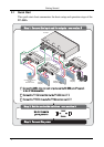
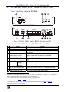
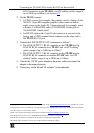
Figure 1 and Table 1 define the TP-305A:
Figure 1: TP-305A UXGA - Audio - RS-232 Line Receiver/DA
Table 1: TP-305A
UXGA - Audio - RS-232 Line Receiver/DA Features
# Feature Function
1 POWER Switch Illuminated switch for turning the unit ON or OFF
2 LINK LED Lights when receiving a valid input signal
3 EQ.
1
Trimmer Adjusts
2
the cable compensation (equalization) level for the
UXGA output
4 LEVEL Trimmer Adjusts
2
the output signal level for the UXGA output
5 LINE IN RJ-45 Connector Connect to the LINE OUT connector of a transmitter
3
6 UXGA OUT 15-pin HD Connector Connect to the video acceptor
7 LINE OUTPUT RJ-45 Connectors Connect to
4
the LINE IN RJ-45 connector on a receiver
5
(from 1
to 5)
8
AUDIO OUT
ANALOG 3.5mm
Mini Jack
Connect to the stereo analog audio acceptor 1
9 S/PDIF RCA
Connector
Connect to the digital audio acceptor 1
10 RS-232 G, Tx Terminal Block Connect the connector (G and Tx) to control a device (see
section 5.3
)
11 Power Connector with Fuse AC connector enabling power supply to the unit
1 Degradation and VGA/XGA signal loss can result from using long cables (due to the effects of stray capacitance, for
example), sometimes leading to a loss of sharpness in high-resolution signals
2 Use a screwdriver to carefully rotate the trimmer, adjusting the appropriate level
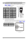
3 The PINOUT is defined in Table 3
and Figure 5
4 Using UTP or STP cable with RJ-45 connectors at both ends (the PINOUT is defined in Table 3
and Figure 5)
5 For example, the Kramer TP-124 or TP-46