


KRAMER: SIMPLE CREATIVE TECHNOLOGY
Connecting the TP-305A UXGA-Audio-RS-232 Line Receiver/DA
6
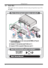
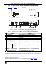
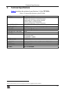
4.1 The TP-305A UXGA - Audio - RS-232 Line Receiver/DA
Underside
Figure 2
and Table 2 define the underside of the TP-305A
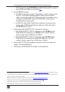
Figure 2: TP-305A Underside
Table 2: Features of the TP-305A Underside
Feature Function
VS Switch
1
Slide the switch down, to set the V SYNC to its input polarity (NORMAL)
Slide the switch up, to set the VS to negative polarity (INVERT)
HS Switch
1
Slide the switch down, to set the HS to its input polarity (NORMAL)
Slide the switch up, to set the HS to negative polarity (INVERT)
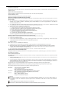
5 Connecting the TP-305A UXGA-Audio-RS-232 Line
Receiver/DA
You can use the TP-305A with a UXGA - Audio - RS-232 Line Receiver/DA
such as the Kramer TP-123
2
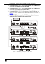
. You can connect a single TP-305A to up to five
receivers, and up to five TP-305A units can be connected to increase the
number of outputs to 25.
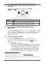
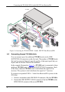
5.1 Connecting a Single TP-305A
To con
nect a TP-123/TP-305A UXGA – Audio - RS-232/Line
Receiver/DA system
3
as illustrated in the example in Figure 3, do the
following
4
:
1. On the TP-305A, connect the:
UXGA OUT 15-pin HD computer graphics video connector to the
UXGA acceptor (for example, a plasma display), and the AUDIO
OUT ANALOG 3.5mm mini jack connector to the analog audio
connector on the acceptor. If required, connect the RS-232 G and
TX terminal block connector to the RS-232 port on the acceptor
LINE OUTPUT RJ-45 connector on the TP-123 to the LINE IN
1 By default, both switches are set to NORM.
2 Refer to the separate user manual, which can be downloaded at: http://www.kramerelectronics.com
3 Using up to 300ft (100m) of UTP cabling
4 Switch OFF the power on each device before connecting it to your TP-305A. After connecting your TP-305A, switch on its
power and then switch on the power on each device