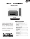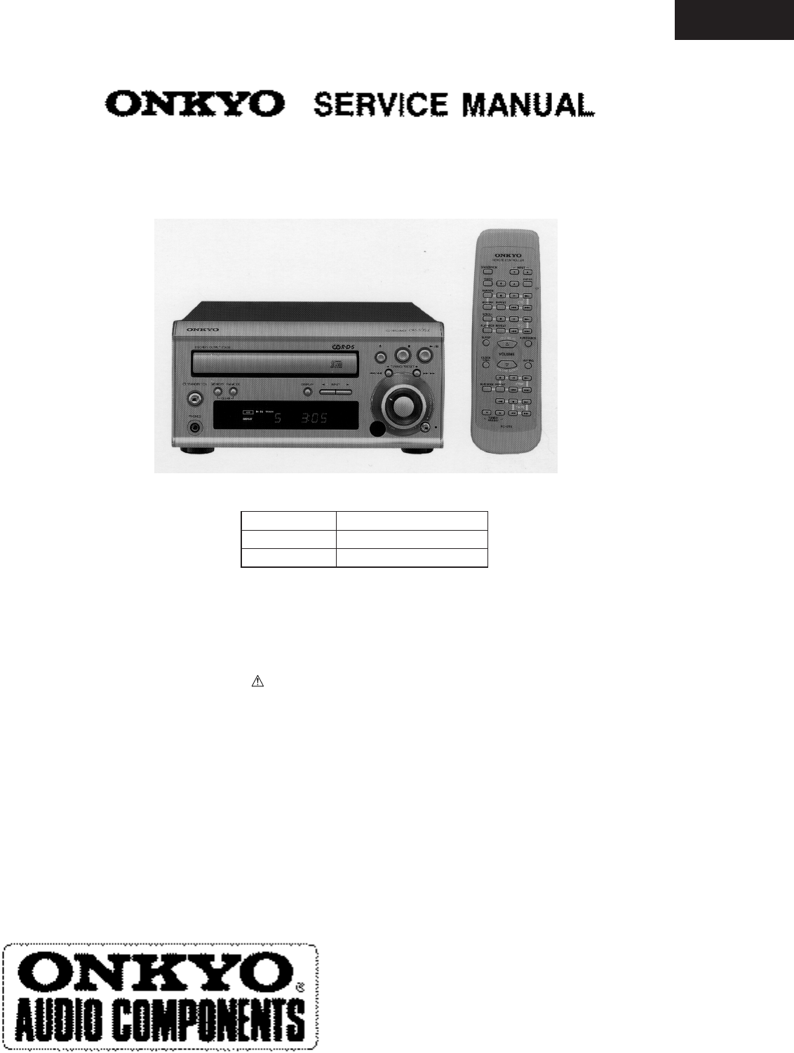
CD RECEIVER
MODEL CR-305X
Ref.NO.3654
082000
TABLE OF CONTENTS
CR-305X
Specifications -----------------------------------------------------------
Caution on replacement of optical pickup --------------------------
Protection of eyes from laser bam during servicing ---------------
Service procedures -----------------------------------------------------
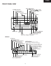
Front panel view ------------------------------------------------------
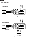
Rear panel view -------------------------------------------------------
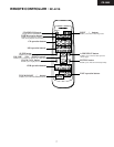
Remote controller ----------------------------------------------------
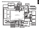
Microprocessor connection diagram --------------------------------
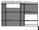
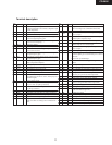
Microprocessor terminal descriptions ------------------------------
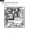
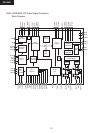
IC Block diagram and descriptions ---------------------------------
CD Mechanism exploded view --------------------------------------
Replacement of optical pickup ---------------------------------------
Chassis exploded view parts list -------------------------------------
Chassis exploded view -----------------------------------------------
Block diagram ---------------------------------------------------------
Wiring view ------------------------------------------------------------
Printed circuit board view parts list --------------------------------7
Schematic diagram (Amplifier section) -----------------------------
Printed circuit board view 1-------------------------------------------
Schematic diagram (CD & Microprocessor section) -------------
Printed circuit board view 2-------------------------------------------
Printed circuit board view 3-------------------------------------------
CD Adjustment procedures ------------------------------------------
Clock adjustment procedures ----------------------------------------
Assembling of pad ---------------------------------------------------
packing view ---------------------------------------------------------
2
2
3
4
5
6
7
8
9
10
19
21
22
23
25
26
27
29
31
33
35
37
39
40
41
42
Silver models
120 V AC,60 Hz
230 V AC,50 Hz
220 - 230 V AC,50/60Hz
UDD,UDT
UPP
UGT,UGR
SAFETY-RELATED COMPONENT WARNING!!
COMPONENTS IDENTIFIED BY MARK ON THE
SCHEMATIC DIAGRAM AND IN THE PARTS LIST
ARE CRITICAL FOR RISK OF FIRE AND ELEC-
TRIC SHOCK. REPLACE THESE COMPONENTS
WITH ONKYO PARTS WHOSE PARTS NUMBERS
APPEAR AS SHOWN IN THIS MANUAL.
MAKE LEAKAGE-CURRENT OR RESISTANCE
MEASUREMENTS TO DETERMINE THAT EXPO-
SED PARTS ARE ACCEPTABLY INSULATED FORM
THE SUPPLY CIRCUIT BEFORE RETURNING THE
APPLIANCE TO THE CUSTOMER.


