


SERVICE PROCEDURE
1. Replacing the fuses
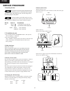
3. Safety-check out
(Only U.S.A. model)
After correcting the original service problem perform the
follwing safety check before releasing the set to the customer
Connect the insulating-resistance tester between the plug of
power supply cord and terminal GND on the back panel.
Specifications: More than 10Mohm at 500V
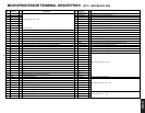
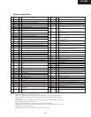
REF.NO.
PART NO.
DESCRIPTION
F901
252157
1.25A-UL/T-237, Fuse <D, DT>
252083
0.4A-SE-EAW, FUSE <P,GR, GT>
NOTE : <D, DT> : 120 V model only
<P,GR, GT> : 230 V model only
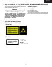
This symbol located near the fuse indicates that the
fuse used is show operating type, For continued protection against
fire hazard, replace with same type fuse , For fuse rating, refer to
the marking adjest to the symbol.
Ce symbole indique que le fusible utilise est e lent.
Pour une protection permanente, n'utiliser que des fusibles de meme
type. Ce demier est indique la qu le present symbol est apposre.
1. Press and the hold down the MEMORY button , then press the
After "all lighting " is displayed
2. Press the standby/on button.
After " CLEAR " is displayed, the preset memory and each mode
stored in the memory, are initialized and will return to the
factory settings.
2. To initialize the unit
4. Memory Preservation
This unit does not require memory preservation batteries. A built-in
memory power back-up system preserves the contents of the
memory during power failures and even when the unit is un-plugged.
The unit must be plugged in order to charge the back-up
system.
The memory preservation period after the unit has been unplugged
varies depending on climate and placement of the unit. On the
average, memory contents are protected over a period of a few
weeks after the last time the unit has been unplugged. This pe-riod
is shorter when the unit is exposed to a highly humid cli-mate.
5. Changing the AM band step
With the exception of the worldwide models, a tuning step selector
switch is not provided. When you change the band step, change
the parts as shown below.
To 10kHz To 9kHz
R705 3.3k 10k
R706 5.6k open
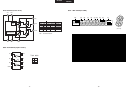
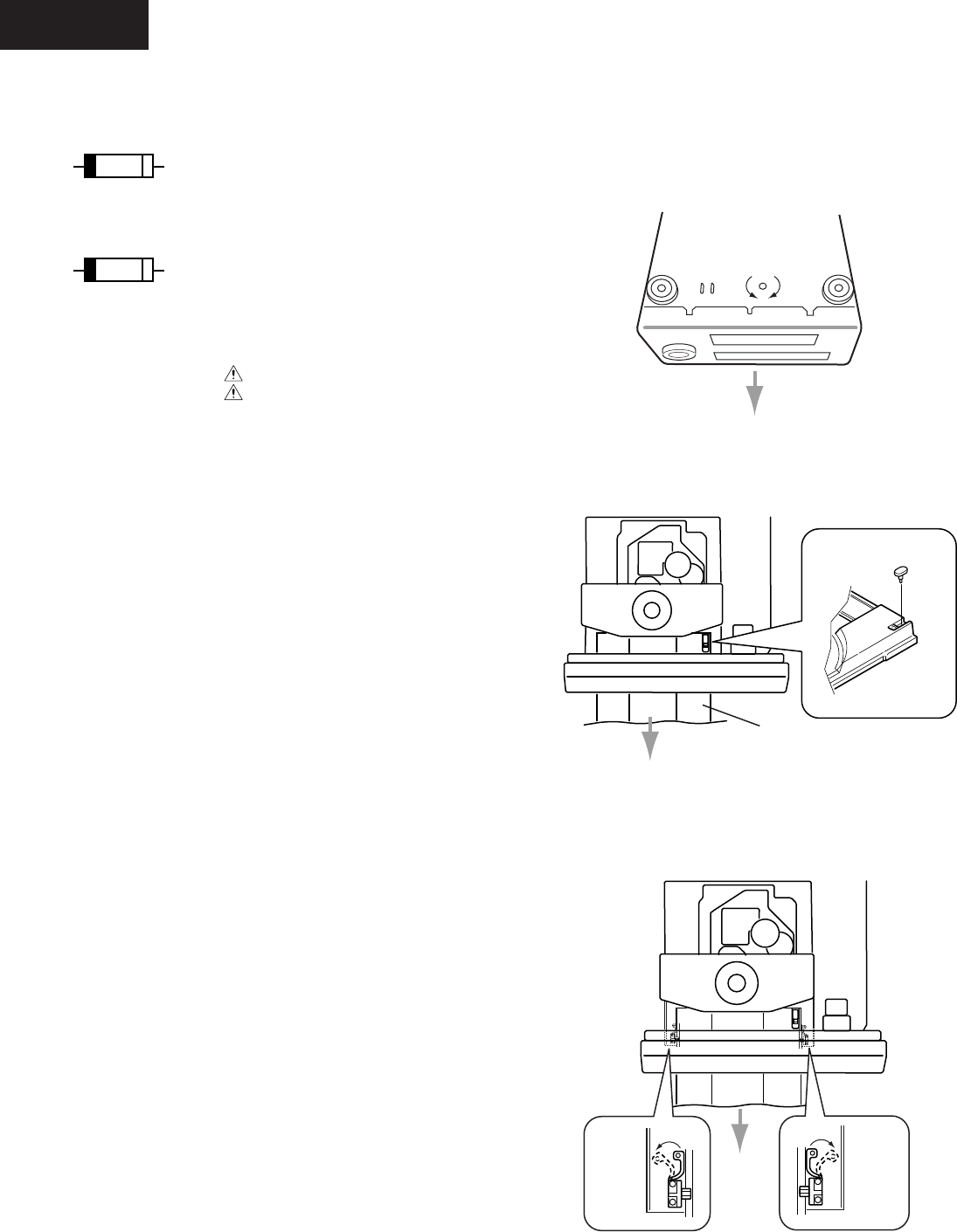
5. Removement of tray
1.Remove the top cover
2.Turn the locked screw to the clockwise to release the lock of gear.
(Refer to fig-1)
Lock
Unlock
Bottom side
Fig-1
3.Pull out the tray.
4.Remove the stopper. (Refer to fig-2)
5.Press teh tray stopper to the arrow mark direction and remove
the tray ass'y. (Refer to fig-3)
Fig-2
Stopper
Tray
Fig-3
Tray
stopper
Tray
stopper
Front
Front
Front
4
CR-305X