


HR20• 12
are marked by polarity and must be installed in the proper direction. You’ll
see that one side of the capacitor has a black band and is marked with a ‘-’
sign. This is the negative side, the other side is the positive lead. Make
sure you insert the positive lead into the ‘+’ marked hole on the PC board.
12. Install C11, a 100-220µF electrolytic capacitor. Remember to observe
correct polarity. C10 and C11 provide voltage stabilizing which directly
improves the performance of the SA602 oscillator.
13. Install C2, 36pF ceramic disc capacitor (marked 36 or 36K). It goes
across pins 6 and 7 of the SA602 IC. This capacitor is the first step in
setting up the resonant frequency of the SA602’s internal oscillator, using
the resonant LC circuit to be created along with C1, C3 and L1.
14. Install C1, 36pF disc capacitor (marked 36 or 36K).
15. Install C3, .01µF disc capacitor (marked 103 or .01 or 10nF).
16. Before installing L2 (marked 42IF-123), its internal capacitor must be
removed just jike you did for L1. Simply crush it completely with a small
screwdriver or a knife. Omitting this step will prevent the oscillator from
tuning the 20 meter band.
17. Install L2, shielded coil.
18. Install C4, a 15pF ceramic disc capacitor. C4 adds variable
capacitance of the varactor tuning network to the oscillator circuit already
formed by L2, C1, C2 and the SA602.
19. Install D1, the 1N4002 diode, making sure that the cathode or banded
end is oriented towards the back of the PC board. This diode performs the
function of a varactor diode. A varactor diode acts like a variable capacitor
whose capacitance is controlled by the the voltage across it. There is
nothing fancy about the varactor diodes, so we are using a common
rectifier.
20. Install R5, 10k ohms (brown-black-orange)
21. Install R2, 10k potentiometer tuning control.
22. Install R3, 10k potentiometer volume control. This control varies the
level of audio from pin 4 of the SA602 to the LM386 audio amplifier.
23. Using a scrap piece of wire, snipped from an installed component,
install JMP-1.
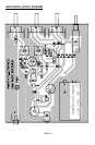
OPTION: with JMP-1 installed the bandspread of your tuning dial is the
normal 250KHz. To get more bandspread in the ham band install C14 as
shown in the parts diagram and install R7 (2.2k) in place of JMP-1.
24. Install S1, the power switch.