


HR20• 22
FREQUENCY STABILITY:
A kilohertz of drift is not a big deal in FM circuits or a shortwave broadcast
configuration, but ANY frequency instability is annoying when trying to receive
CW or SSB. The varactor - controlled Local Oscillator is indeed a VFO, and
therefore needs all the consideration given to any VFO circuit. Even though
this tunable oscillator design takes good advantage of the SA602’s capabilities
and offers nice tuning range from a simple varactor circuit, we do not
represent it as suitable for transmitter frequency control or for demanding
receiver applications. In any ham VFO design, ANY unshielded or
uncompensated oscillator components are susceptible to the influences of
temperature change and of nearby moving objects. The use of a suitable
enclosure and secure mounting of the PC board within that enclosure will
maximize the stability of the oscillator. One to two KHz of slow drift may be
expected as components warm to operating temperature; after that the
oscillator is reasonably stable.
OTHER METHODS OF DIAL CALIBRATION:
A easy way of making your own dial is to paste a small rectangle of paper
behind the tuning dial knob. Then as you tune in different frequencies, pencil
in on the paper the received frequency. Or a simple logging scale may be
affixed behind the tuning knob on the front panel. A logging scale is simply a
set of numbers for adjusting a control. For example, 4 might represent 7.1MHz
and 5.5 being 7.12MHz, and so forth.
DIRECT FREQUENCY READOUT:
A novel advantage of the simple direct conversion receiver is that a general
purpose frequency counter may be used to give a direct readout of the
oscillator frequency. While you could experiment with an RF pickup loop or
tuned circuit and counter preamplifier to boost the oscillator’s tiny output to a
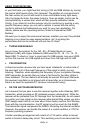
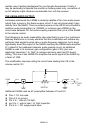
level suitable for the counter, the most reliable method is to wire a high-
impedance counter probe line directly to pin 7 of the SA602, terminated to a
rear panel frequency counter connection of your choice. This will consist of a
short piece of mini-coax to a 1 megohm resistor bridged by a 27 to 33pf
capacitor as shown below:
With the RF gain turned all the way up , it may be possible to hear the
counter’s busy humming action in the background, but not to a serious
degree. It drops out with a slight reduction of the RF gain. If you decided to
add such a counter connection to your receiver, remember that the coax as
well as the coupling capacitor become part of the oscillator circuit. Make the
coaxial cable connecting the counter to the receiver as short as possible. You
will experience a frequency change of several KHz when connecting or
disconnecting the counter. Also, this additional capacitance in the oscillator
circuit reduces the tuning range to approximately 100 KHz, thus offering