HR20• 23
another way of getting bandspread for your favorite frequencies. Finally, it
may be necessary to operate the counter on battery power only; connection of
an AC adapter might introduce considerable hum into the receiver.
THE LM386 AUDIO OUTPUT:
As already mentioned the LM386 is certainly capable of far more audio power
output than is given in this basic receiver circuit. It can only boost what it gets
directly from the SA602. There is certainly space on the HR-30 circuit board to
install an audio preamplifier (i.e. 2N3904, or minimum-gain LM386) in the
circuit trace between C8, the audio-coupling capacitor from pin 4 of the SA602
to the volume control.
The following is an audio preamplifier idea submitted by one of our customers.
Ramsey Electronics in no way warrants that this modification will achieve any
particular ideal signal-to-noise ratio or audio frequency response, but is does
significantly boost the output of the SA602 reaching the LM386 audio amplifier
IC. Instead of the traditional transistor audio preamp circuit, an additional
LM386 is used in its minimum gain configuration (gain of 40), plus one
electrolytic capacitor (1 to 10µF) to achieve minimum parts and PC-board
drilling. This use of two LM386 ICs amplifies the audio signal of the SA602 by
a factor of 1000.
This modification requires cutting the circuit trace leading from C8 to the
volume control, R3
Additional LM386 used as AF preamplifier between U1 and U2:
Pins 1,7,8: not used
Pins 2,4: to ground
Pin 3 to ‘-’ side of c*(2.2pF)
pin 5 to ‘+’ side of new 1 to 10µF capacitor
Pin 6 to ‘+’ DC supply board trace
1
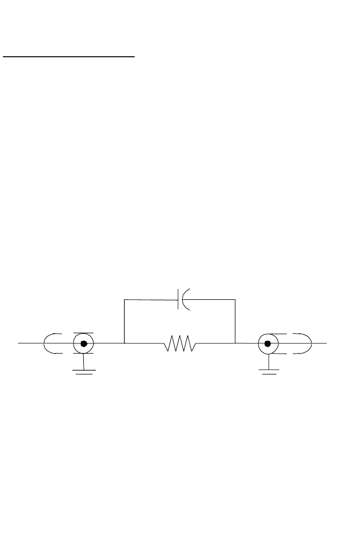
MEGOH
NE60
2
PIN
7
COUNT
ER
TO
27
pF


