


HR20• 8
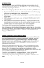
"LEARN-AS-YOU-BUILD" RECEIVER ASSEMBLY STRATEGY:
To help you learn just what exactly is going on we'll discuss the purpose of
most of the components or groups of components as we go along. Since we
are trying to keep assembly of the board simple, we will not be able to fully
describe each individual component’s function as you build, but Ramsey's
"Learn-As-You-Build" kit assembly philosophy still stands.
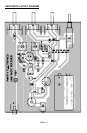
Check off each step as understood and completed. Examine the schematic
diagram and PC-board X-ray illustration as you proceed. In all steps, “install”
means to insert into the correct PC-board holes, solder properly, and trim all
excess component leads.
Use good soldering skills - let your soldering iron heat each connection wire
so that the wire itself and the foil trace both become hot enough together to
melt the applied solder so that it flows smoothly around the wire lead and on
to the PC board trace.
Mount all electrical parts on the top side of the board provided. This is the
side that has no traces or pads on it. When parts are installed, they are placed
flat to the board, and the leads are bent on the backside of the board to
prevent the part from falling out before soldering. The part is then soldered
securely to the board, and the remaining lead length is then clipped off. The
clipped off leads should be saved for later use as jumper wires.
As you can see in examining the circuit board and parts there are many tall
components such as the potentiometer, capacitors, and switches along with a
lot of small parts. First you will install the larger components so they can be
used as markers. So that you don't spend extra time "troubleshooting" we
strongly recommend that you follow the assembly strategy and step-by-step
procedures we have provided.